|
|
|||
|
February 2016 • Vol.5, Issue 1 |
|||
|
H New MRI Safety Labels & Devices
|
|||
|
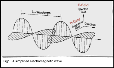
B1+rms as a Condition of Use When performing an MRI exam on patients implanted with an MR Conditional active implant and/or device, it is often critical to be aware of, and control the amount of RF power utilized. Historically, the metric utilized for this purpose has been SAR. However, SAR has been shown to not be an accurate metric for RF-induced heating relating to implants and devices1. SAR (Specific Absorption Rate) is a measure of the rate at which RF energy is deposited in tissues. As the term describes; it is specific to the body part, and it is what is absorbed over time. SAR is estimated by the MRI system software, and it is estimated for each sequence. We know that SAR is proportional to the power of 2 for the resonant frequency. Therefore, doubling the field strength (for example going from 1.5 T to 3.0 T) will result in a fourfold increase in SAR. We know that SAR is proportional to the power of 2 for the amplitude of the RF pulse. This means that doubling the flip angle will result in a fourfold increase in SAR. SAR is also proportional to the power of 5 for a patient’s circumference and proportional to the average conductivity of a patient. No universal standard is in place for estimating SAR. Therefore, the method, calculations and resultant value reported will vary with the MR equipment manufacturer. Each manufacturer uses their own assumptions regarding the patients size and tissue composition to estimate the SAR. Based on these known factors, regarding SAR estimation, we expect that displayed SAR values will vary greatly depending on the patient and the MR equipment vendor. So in summary, a small patient with a given MR conditional implant or device will have a different displayed SAR value than a larger patient with the same implant or device. Additionally, the same patient with a given MR conditional implant or device will have different SAR values on different MR systems even if the acquisition parameters are identical. Furthermore, although it varies, the SAR estimates by the MR system vendors is extremely conservative. Using a low SAR value (such as 0.1 W/kg) can greatly limit the sequence and parameter options one can utilize. This can easily adversely affect the overall quality and clinical usefulness of the MR exam. A Joint Working Group, comprised of engineers and scientists from MR equipment and device manufacturers along with the FDA have recommended B1+rms be used as a metric for device heating as opposed to SAR. B1+rms is the average effective RF magnetic field generated by the RF transmit coil for a given pulse sequence. The B1+rms is calibrated by the MR system software during the “prep” or “pre-scan” phase or measurements. B1+rms is patient independent and it is determined by basic MRI requirements. It is interesting to note that B1+rms is used in every MR system manufacturers SAR calculations. To further explain B1+rms, recall that RF pulses are used to excite hydrogen protons and cause the net magnetization to rotate it through a specific angle which we typically refer to as the “flip angle”. This RF pulse is an electromagnetic wave which consists of an electric field (the E-field) and a magnetic field (the B-field). A simple electromagnetic wave is shown in figure 1.
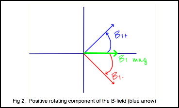
In MRI, it is a component of the magnetic field that we use to excite the protons. The E-field doesn’t do anything for imaging but only contributes to heating. The B-field can be decomposed into two rotating components or vectors (figure 2). In the diagram, the blue vector represents the positively rotating component and the red vector represents the negatively rotating component. The green vector represents the vector sum of the two. It is actually only the positively rotating component that excites the protons. The negative component has no effect regarding the excitation of the protons.
Root mean square (rms) is also known as the quadratic mean. It is a statistical measure of the magnitude of a varying quantity. It is especially useful when the variates are positive and negative such a sinusoid (like our B-field). Therefore, B1+rms is a measure of the magnitude of the positive rotating component of the B-field. B1+rms is expressed in units of microtesla (uT). An important characteristic of B1+rms is that it is not an estimated value but a known value based on the pulse sequence and the associated parameters. It is not patient dependent nor is it calculated differently based on the MR system manufacturer. A given B1+rms value on system A is the same on system B. In 2013, the IEC (International Electrotechnical Commission) mandated all MR systems manufactured going forward must display the B1+rms1. It was not mandated to update older systems to display the B1+rms. Therefore this will not be displayed on all MR system currently in use. Some manufacturers, however, have modified certain older systems to display B1+rms. B1+rms as a Condition of Use Given that B1+rms is a more precise RF exposure metric than SAR, device manufacturers have begun to have labeling approved with a given B1+rms value not to be exceeded. When following B1+rms as a condition of use, the SAR value is irrelevant (unless a particular operating mode is specified). If your particular MR system does not display B1+rms, then SAR limits must be maintained as per the device labeling. How one modifies scan parameters to affect the B1+rms will vary somewhat between MR system brands. However, in general terms, whatever you do to reduce SAR on your system will likely reduce the B1+rms. If your system displays B1+rms, you will find it in the same area which you find SAR. Here are a few examples.
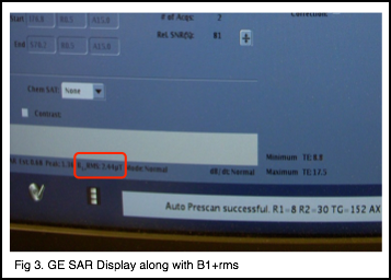
Figure 3 shows where B1+rms is displayed on this particular version of software. Again, it is adjacent to the SAR value. Also remember, not all versions of software (particularly the older versions) will display B1+rms.
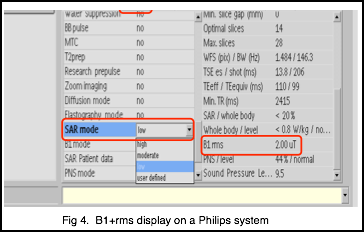
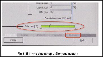
Figure 4 shows where the B1+rms is displayed on a Philips system and Figure 5 is the display on a Siemens system. As previously stated, the exact parameters one uses to modify B1+rms will vary with the particular MR system. However, some examples of parameters and options one can adjust to reduce B1+rms include:
Again, not all of these options will be available on every MR system. Read your user manual or contact your MR vendors clinical education specialists for information about your specific system. Aside from being a more precise RF exposure metric than SAR, another advantage to using B1+rms as opposed to SAR is that once you adjust a particular sequence to a desired B1+rms value, you can save it in your protocol library. It will then remain at that value for the next patient (unless you alter the scan parameters). This is not possible with SAR as SAR will vary depending on the patient. In summary B1+rms is now beginning to be used by device manufactures in their MR conditional labeling. Education is important in order to understand B1+rms and know how to adjust your protocols to achieve a desired B1+rms value for the safety of your patients. As a member benefit, the SMRT makes available, safety videos and other materials which are a valuable resource for todays MRI Technologists. Wm. Faulkner,
BS,RT(R)(MR)(CT), FSMRT, MRSO (MRSC™)
1 International Electrotechnical Commission. IEC 60601-2-33:2010+A11:2011 and Corrigendum 1:2012. Medical electrical equipment. Part 2-33: Particular requirements for the basic safety and essential performance of magnetic resonance equipment for medical diagnosis. 3rd. Geneva: International Electrotechnical Commission, 2010 |
|||
|
Signals is a publication produced four times per calendar year by the International Society for Magnetic Resonance in Medicine for the benefit of the SMRT membership and those individuals and organizations that support the educational programs and professional advancement of the SMRT and its members. The newsletter is the compilation of editor, Julie Strandt-Peay, BSM, RT (R)(MR) FSMRT, the leadership of the SMRT and the staff in the ISMRM Central Office with contributions from members and invited participants. |