Grant Kaijuin Yang1,2, Ek Tsoon Tan3, Eric Fiveland4, Thomas Foo4, and Jennifer McNab2
1Electrical Engineering, Stanford University, Stanford, CA, United States, 2Radiology, Stanford University, Stanford, CA, United States, 3Hospital for Special Surgery in Manhattan, New York, NY, United States, 4GE Global Research, Niskayuna, NY, United States
1Electrical Engineering, Stanford University, Stanford, CA, United States, 2Radiology, Stanford University, Stanford, CA, United States, 3Hospital for Special Surgery in Manhattan, New York, NY, United States, 4GE Global Research, Niskayuna, NY, United States
Q-space trajectory imaging was implemented and tested on the MAGNUS gradient system.

Figure 3: (a) µFA maps from MAGNUS with full 200mT/m gradients, 50mT/m gradients, and MR750 with 50mT/m systems. MAGNUS demonstrates lower distortion in the prefontal cortex (red arrow) due to the shorter effective echo spacing. Slice coverage is also improved due to the reduced gradient heating of the head-only gradient. (b) Histogram of tSNR values within the white matter calculated from the 22 non-diffusion weighted image volumes (top) and 60 b=2000s/mm2 isotropic diffusion weighted volumes from the read-out time matched MAGNUS-A2 (blue) and MAGNUS-B acquisitions (orange).
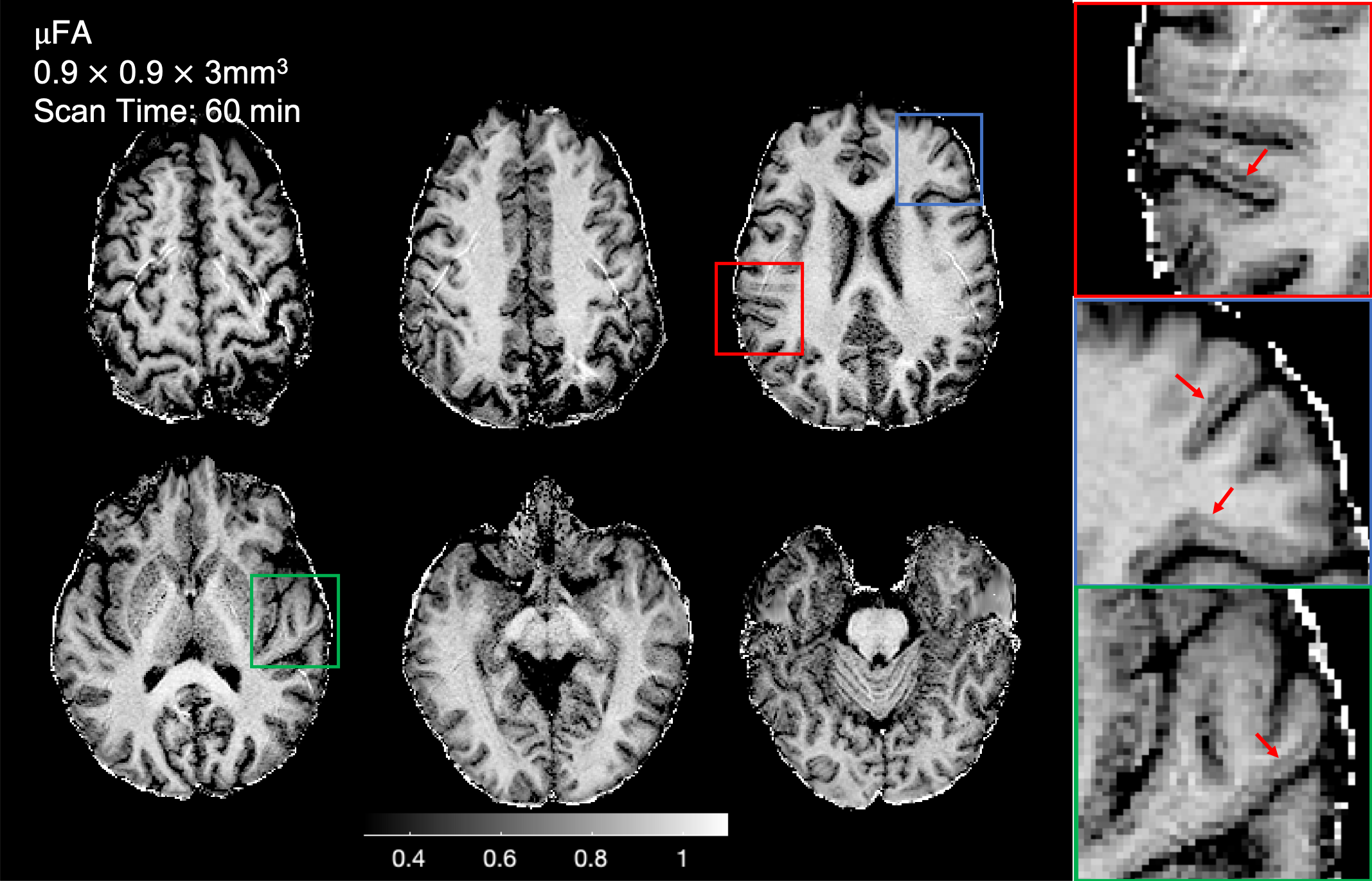
Figure 2: Representative slices from the combined data from the two 30 min MAGNUS-A1 acquisitions with sub-millimeter in-plane resolution. The µFA maps are significantly higher resolution and show fine details in the transition between the white matter and cortex (magnified regions), which are inaccessible at lower resolutions. However, some parallel imaging artifacts are present due to uncorrected first order concomitant fields resulting from the asymmetric gradient coil design.