Nikolai Avdievich1, Georgiy Solomakha2, Loreen Ruhm1, Anke Henning1,3, and Klaus Scheffler1
1High-field Magnetic Resonance, Max Planck Institute for Bilogical Cybernetics, Tübingen, Germany, 2Physics and Engineering, ITMO University, St. Petersburg, Russian Federation, 3Advanced Imaging Research Center, University of Texas Southwestern Medical Center, Dallas, TX, United States
1High-field Magnetic Resonance, Max Planck Institute for Bilogical Cybernetics, Tübingen, Germany, 2Physics and Engineering, ITMO University, St. Petersburg, Russian Federation, 3Advanced Imaging Research Center, University of Texas Southwestern Medical Center, Dallas, TX, United States
Transmit
dipoles can be decoupled by passive antennas placed parallel between them. Such
passive dipoles interact destructively with the RF field of the array. In this
work, we developed a novel decoupling method of transmit dipoles by using
modified perpendicular passive dipole antennas.
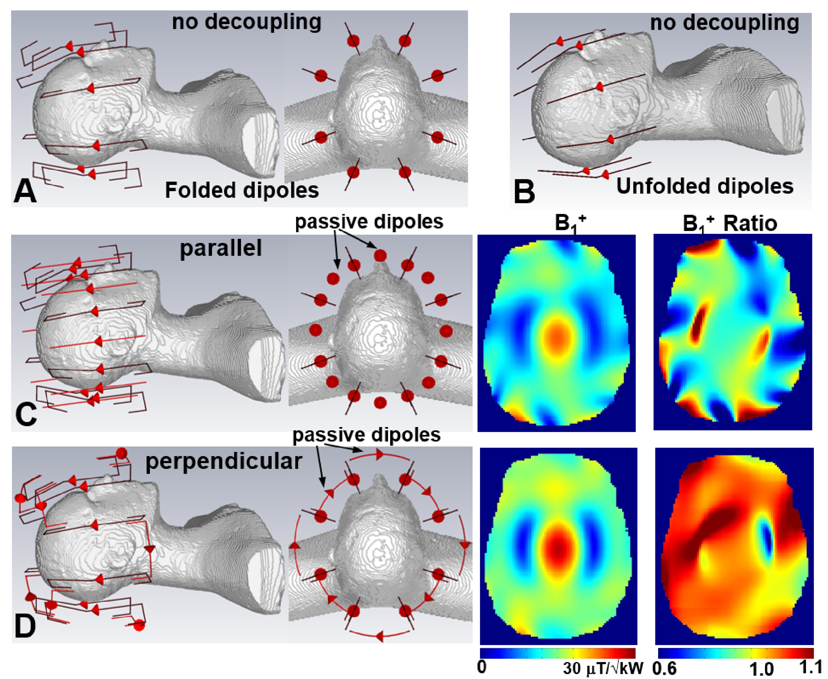
Figure 2. CST simulation models of the folded-end (A) and unfolded (B) dipole
arrays without decoupling. CST simulation models and results (B1+, B1+
ratio) for 1x8 bent folded-end dipole arrays decoupled using the common
parallel dipoles (C) and modified perpendicular dipoles (D). All arrays are
loaded by the head and shoulder (HS) phantom. Transmit dipoles and passive
dipoles are shown in black and red, respectively. B1+
ratio is calculated by dividing corresponding B1+ maps by
one obtained using the array without decoupling (Fig.2A).
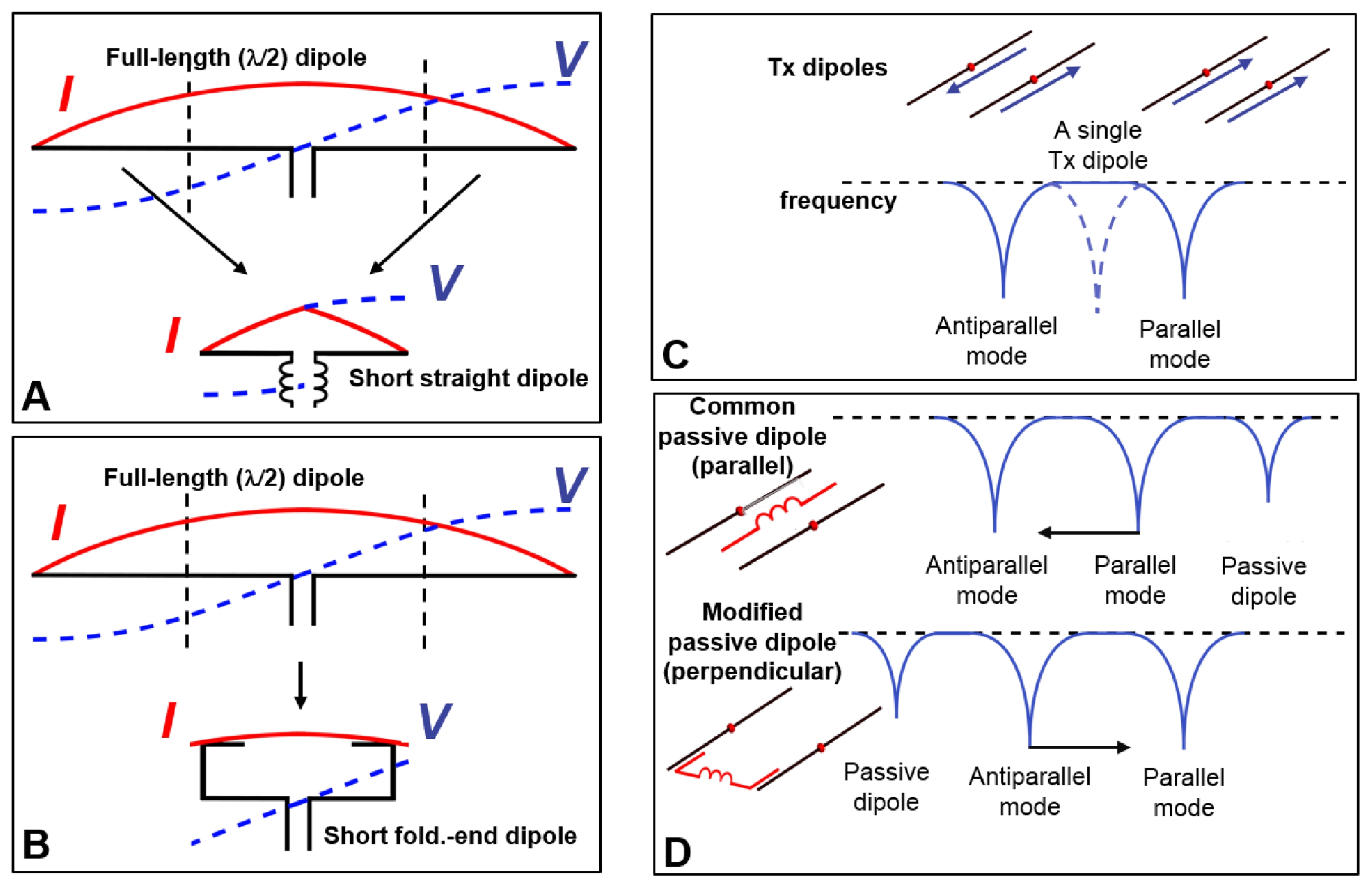
Figure 1. A) Current and voltage
distributions along the length of the full-length dipole vs a “short” dipole.
B) Current and voltage distributions along the length of a folded-end dipole.
C) Two modes of a pair of coupled dipole antennas. Dashed curve shows the
resonance line of a single dipole. D) General representation of the decoupling
effect produced by an addition of the common straight parallel (top) and
modified perpendicular (bottom) passive dipoles both shown in red. To increase
the electrical length, both passive dipoles have a lumped-element inductor
connected in series.