David A Feinberg1,2,3, Peter Dietz4, Chunlei Liu1,5, Kawin Setsompop6, Pratik Mukherjee7,8, Lawrence L Wald9,10,11, An T Vu7,8, Alexander JS Beckett1,2, Ignacio Gonzalez Insua4, Martin Schröder4, Stefan Stocker4, Paul H Bell12, Elmar Rummert4, and Mathias Davids9,10,13
1Helen Wills Neuroscience Institute, University of California, Berkeley, CA, United States, 2Advanced MRI Technologies, Sebastopol, CA, United States, 3Department of Cognitive Neuroscience, Maastricht University, Maastricht, Netherlands, 4Siemens Healthcare GmbH, Erlangen, Germany, 5Department of Electrical Engineering and Computer Sciences, University of California, Berkeley, CA, United States, 6Radiological Sciences Laboratory, Stanford University, Stanford, CA, United States, 7Radiology, University of California, San Francisco, CA, United States, 8San Francisco Veteran Affairs Health Care System, San Francisco, CA, United States, 9A.A. Martinos Center for Biomedical Imaging, Dept. of Radiology, Massachusetts General Hospital, Charlestown, MA, United States, 10Harvard Medical School, Boston, MA, United States, 11Harvard-MIT Division of Health Sciences Technology, Cambridge, MA, United States, 12Siemens Medical Solutions USA, Inc, Cary, NC, United States, 13Computer Assisted Clinical Medicine, Medical Faculty Mannheim, Heidelberg University, Heidelberg, Germany
1Helen Wills Neuroscience Institute, University of California, Berkeley, CA, United States, 2Advanced MRI Technologies, Sebastopol, CA, United States, 3Department of Cognitive Neuroscience, Maastricht University, Maastricht, Netherlands, 4Siemens Healthcare GmbH, Erlangen, Germany, 5Department of Electrical Engineering and Computer Sciences, University of California, Berkeley, CA, United States, 6Radiological Sciences Laboratory, Stanford University, Stanford, CA, United States, 7Radiology, University of California, San Francisco, CA, United States, 8San Francisco Veteran Affairs Health Care System, San Francisco, CA, United States, 9A.A. Martinos Center for Biomedical Imaging, Dept. of Radiology, Massachusetts General Hospital, Charlestown, MA, United States, 10Harvard Medical School, Boston, MA, United States, 11Harvard-MIT Division of Health Sciences Technology, Cambridge, MA, United States, 12Siemens Medical Solutions USA, Inc, Cary, NC, United States, 13Computer Assisted Clinical Medicine, Medical Faculty Mannheim, Heidelberg University, Heidelberg, Germany
The scanner is integrated with an asymmetric head gradient coil designed with 3-layers of windings to achieve in-vivo Gmax 200 mT/m and Smax 900 T/m/s. The 128-channel receiver system enables use of high density arrays for greater sensitivity in cortex and higher accelerations.
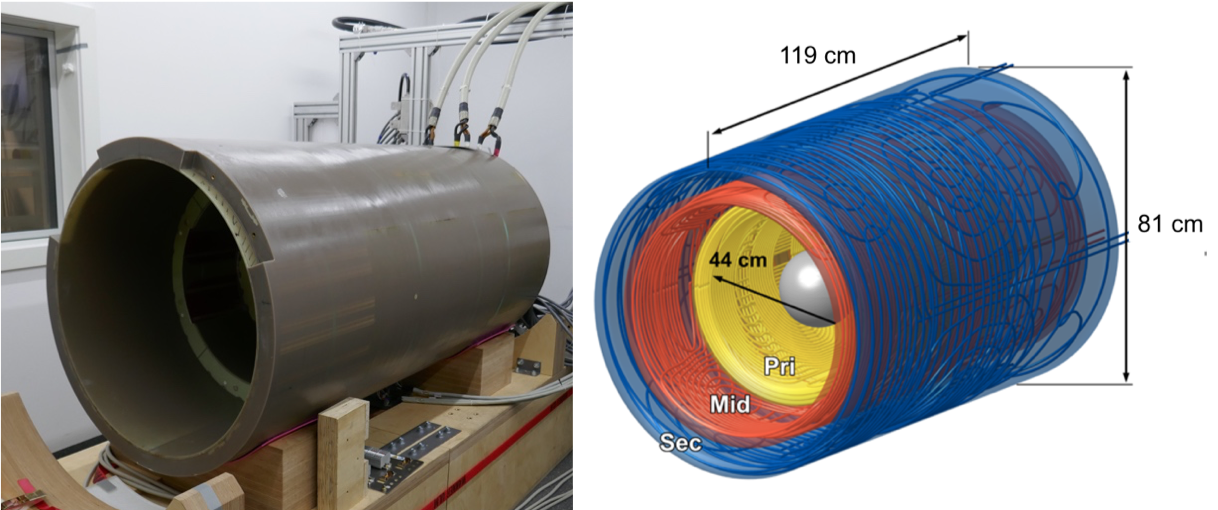
Figure 2 - Left) Photo of gradient coil with 3 stepped layers. The overall mechanical length of the gradient coil is 160 cm to mount easily inside magnet and for better dynamics. The total extent of the wires in Z direction is 119 cm. Right) Plot of wiring pattern showing 3 layers as primary (Pri), intermediate (Mid) and secondary (Sec) layers in stepped design.
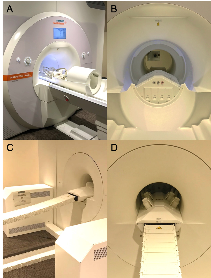
Figure 1 - Photos of the scanner. A) Front side of scanner showing RF cables connecting the 96-ch Rx, 16-ch Tx coil to 128-ch interface box. B) gradient coil cover with shoulder cut outs with the coil interface box in front. The front bore is 60 cm diameter for subject access. C) Photo of energy chain between two 64-ch RF receiver interfaces. D) The rear bore is 39 cm diameter. The coil interface box is positioned in the rear of the magnet bore when the RF coil is positioned at isocenter. The flat flexible energy chain shields over 270 cables and is seen connected to the coil interface box.