Xinqiang Yan1,2, Steven P. Allen3, Craig H. Meyer3, and William A. Grissom1,2,4
1Vanderbilt University Institute of Imaging Science, Nashville, TN, United States, 2Department of Radiology and Radiological Sciences, Vanderbilt University Medical Center, Nashville, TN, United States, 3Department of Biomedical Engineering, University of Virginia, Charlottesville, VA, United States, 4Department of Biomedical Engineering, Vanderbilt University, Nashville, TN, United States
1Vanderbilt University Institute of Imaging Science, Nashville, TN, United States, 2Department of Radiology and Radiological Sciences, Vanderbilt University Medical Center, Nashville, TN, United States, 3Department of Biomedical Engineering, University of Virginia, Charlottesville, VA, United States, 4Department of Biomedical Engineering, Vanderbilt University, Nashville, TN, United States
The “propeller-beanie” antenna method can significantly alleviate the dark band
artifacts in in vivo imaging in a Insightec tcMRgFUS system, which improves temperature precision
and may enable the use of diffusion imaging to monitor treatment.
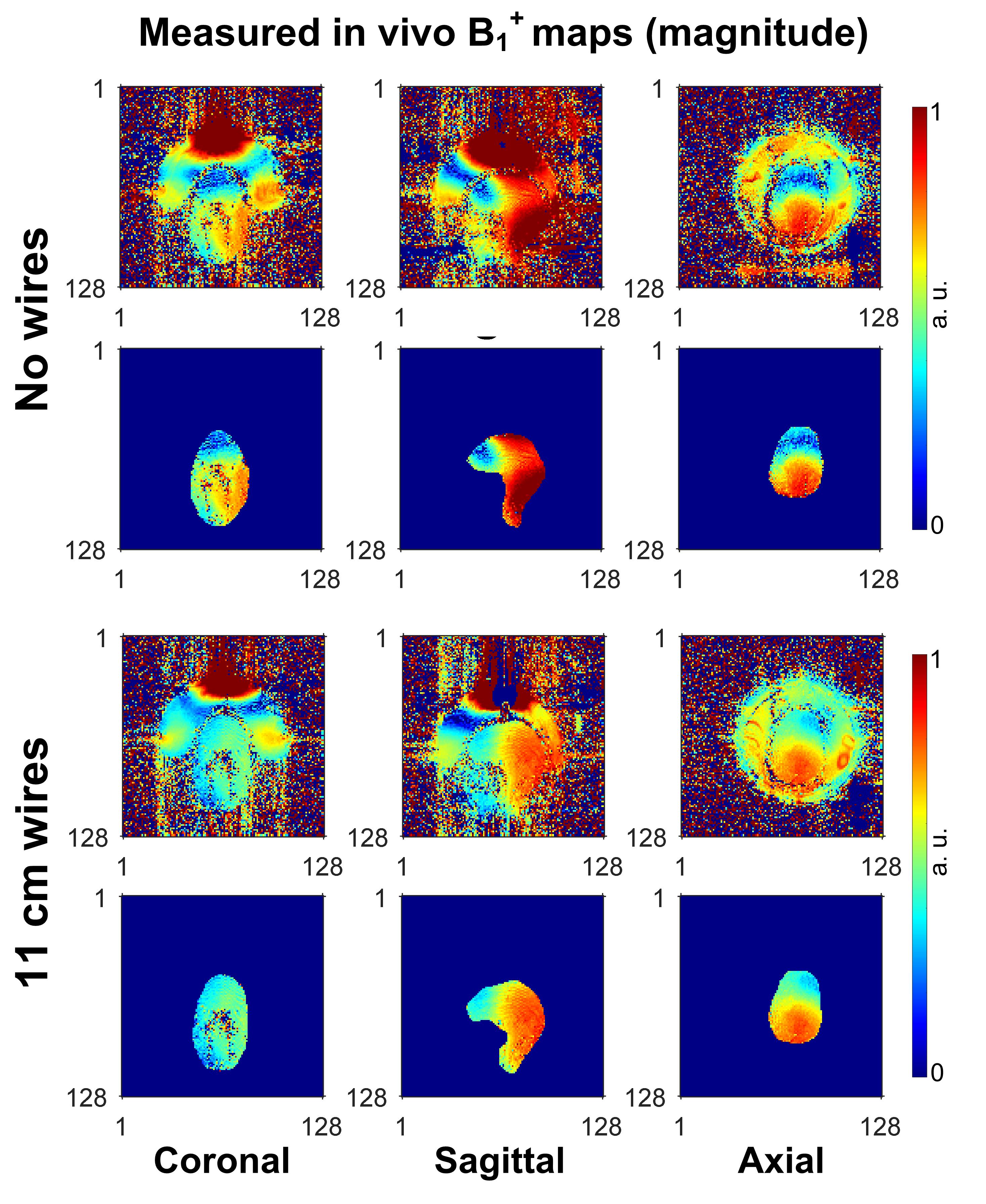
Figure
3 In
vivo transmit RF field (B1+) maps in coronal, sagittal and axial planes. Top:
without passive wires. Bottom: with 11-cm-long passive wires. The
full-FOV maps including the water bath are shown in the first row of each case,
and maps masked to the brain are shown in the second row of each case. By using 11-cm wires, the B1+ uniformity was considerably improved. However,
it is also noted that the B1+ is still not so uniform as that of in simulation. This could be attributed to the fact that wires deviated from the central position in the axial plane.
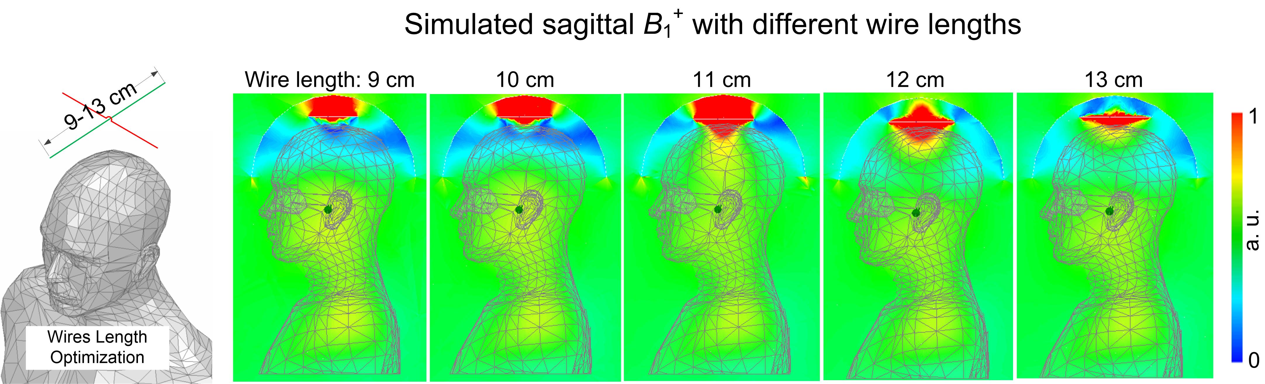
Figure 2 Optimization setup to evaluate the best length for the passive wires (left) and the simulated RF transmit magnitude (|B1+|) maps. The optimal wire length was 11 cm (highest B1+ efficiency near the middle of the brain) which was used for the in vivo experiments.
