Mert Şişman1, Mehdi Sadighi1, Hasan Hüseyin Eroğlu2,3, and B. Murat Eyüboğlu1
1Electrical and Electronics Engineering, Middle East Technical University (METU), Ankara, Turkey, 2Danish Research Centre for Magnetic Resonance, Centre for Functional and Diagnostic Imaging and Research, Copenhagen University Hospital, Amager and Hvidovre, Denmark, 3Center for Magnetic Resonance, DTU Health Tech, Technical University of Denmark, Kgs Lyngby, Denmark
1Electrical and Electronics Engineering, Middle East Technical University (METU), Ankara, Turkey, 2Danish Research Centre for Magnetic Resonance, Centre for Functional and Diagnostic Imaging and Research, Copenhagen University Hospital, Amager and Hvidovre, Denmark, 3Center for Magnetic Resonance, DTU Health Tech, Technical University of Denmark, Kgs Lyngby, Denmark
Magnetohydrodynamic
(MHD) flow occurs due to the Lorentz force formed by the interaction between the
static magnetic field of the MR scanner and the externally injected electric current. In
this study, simulated and experimental MHD
flow velocity distributions are obtained and validated.
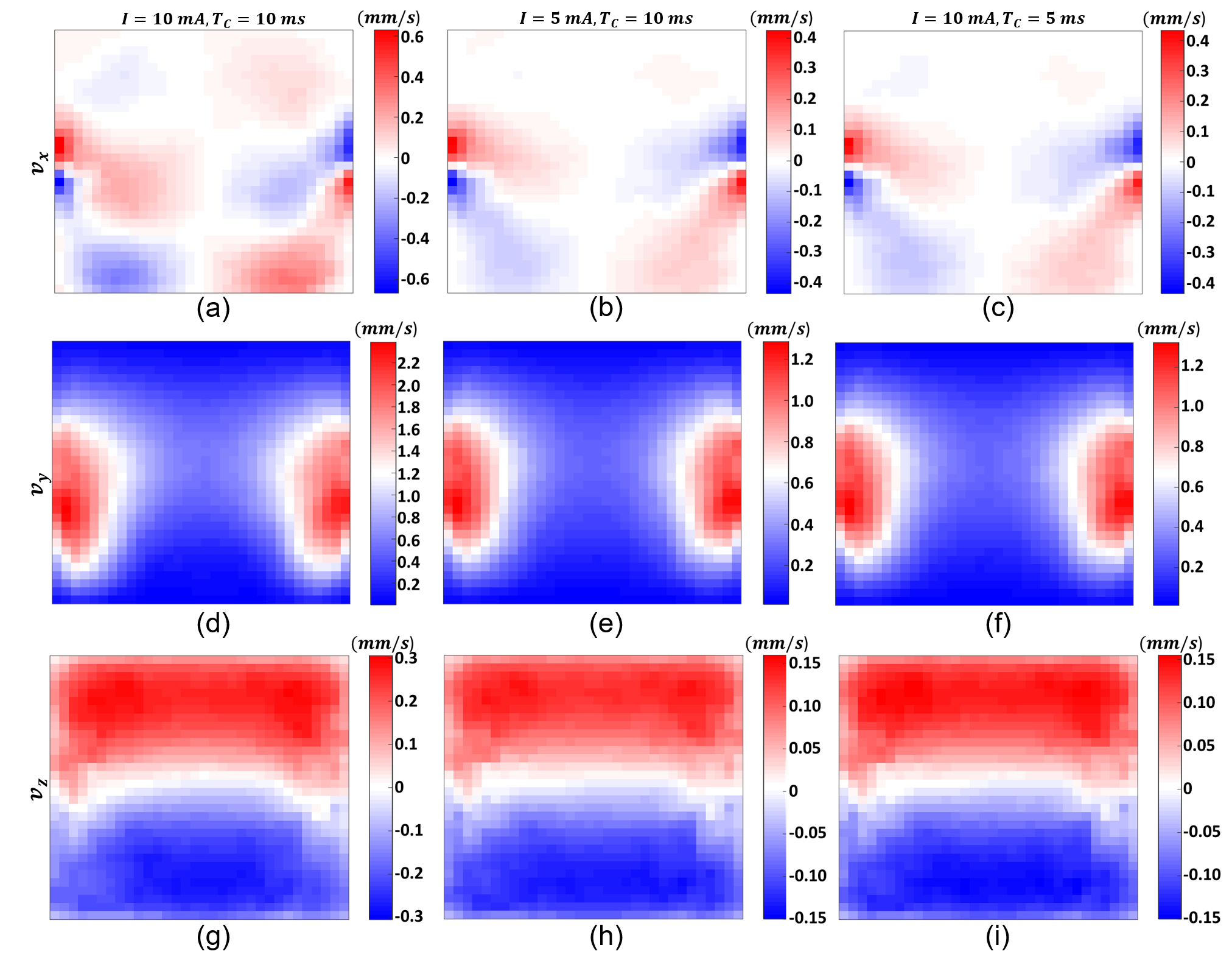
Figure 5: MHD flow velocity distributions of the homogeneous experimental phantom: x-component with current injection parameters (a) I = 10 mA, TC = 10 ms, (b) I = 5 mA, TC = 10 ms, and (c) I = 10 mA, TC = 5 ms; y-component with current injection parameters (d) I = 10 mA, TC = 10 ms, (e) I = 5 mA, TC = 10 ms, and (f) I = 10 mA, TC = 5 ms; and z-component with current injection parameters (g) I = 10 mA, TC = 10 ms, (h) I = 5 mA, TC = 10 ms, and (i) I = 10 mA, TC = 5 ms.
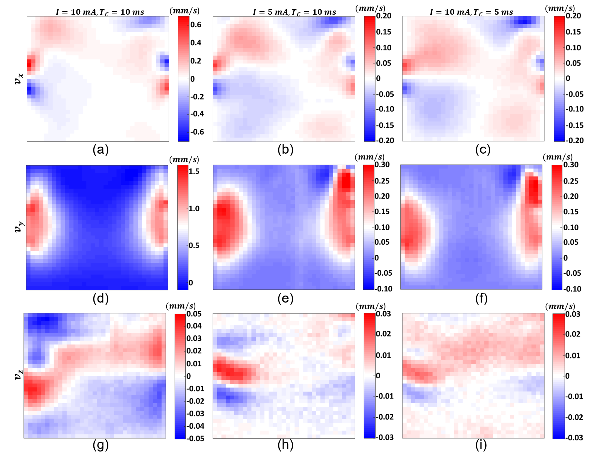
Figure 4: MHD flow velocity distributions of the homogeneous simulation model:
x-component with current injection parameters (a) I = 10 mA, TC = 10 ms, (b) I = 5 mA, TC = 10 ms, and (c) I = 10 mA, TC = 5 ms; y-component with current injection parameters (d) I = 10 mA, TC = 10 ms, (e) I = 5 mA, TC = 10 ms, and (f) I = 10 mA, TC = 5 ms; and z-component with current injection parameters (g) I = 10 mA, TC = 10 ms, (h) I = 5 mA, TC = 10 ms, and (i) I = 10 mA, TC = 5 ms.