Carel C. van Leeuwen1, Bart R.E. Steensma1, Dennis W.J. Klomp1, Cornelis A.T. van den Berg1, and Alexander J.E. Raaijmakers1,2
1University Medical Center Utrecht, Utrecht, Netherlands, 2Biomedical Engineering, Eindhoven University of Technology, Eindhoven, Netherlands
1University Medical Center Utrecht, Utrecht, Netherlands, 2Biomedical Engineering, Eindhoven University of Technology, Eindhoven, Netherlands
The ‘coax
dipole antenna’, a flexible dipole antenna made from coaxial cables is
presented. It achieves B1 levels similar to a reference, while producing 18% lower
SAR levels. T2 weighted prostate images were acquired from 3 volunteers.
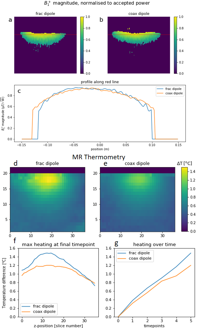
Results of measurements
performed on a phantom with a single antenna. (a,b) saggital slices of B1 maps
(method: DREAM16 FA/steFA/TE/TR 10/60/1.4/4 ms). (c) profile of B1 magnitude along red lines in figures a and b.
(d,e) Temperature maps at the final timepoint, based on proton resonance
frequency shift17. (FA/TE/TR 110/10/15 ms, heating with 20 W
average power, duty cycle 10%, 100 kHz off resonance block pulses) (f) maximum
heating as a function of z-position. (g) maximum heating in the whole volume,
as a function of time.
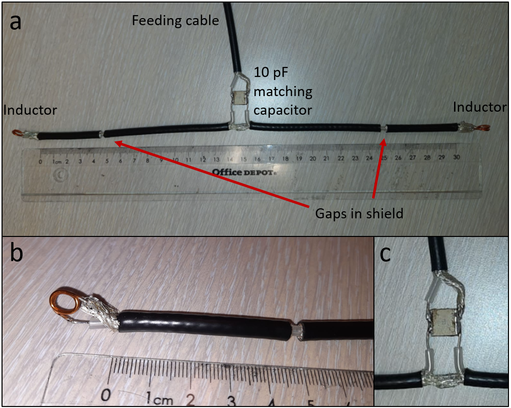
Photographs
of the constructed antenna. Cable type: Huber Suhner RG223u (a) Overview of the
antenna, with various components as indicated and a ruler for scale. (b).
Close-up of one of the ends. Inductors at the end were hand-wound using 4 mm
long sections of annealed copper wire. The correct inductance value was
determined by measuring the reflection at the port and choosing the inductance
value that results in an admittance such that Re(Y) = 1/50 S. (c) Matching
Circuit.