Mike Twieg1
1Hyperfine Research, Guilford, CT, United States
1Hyperfine Research, Guilford, CT, United States
Here we describe a method for driving low-frequency RF
switches. The circuit is compact, low cost, and does not rely on any ferrous
materials or high frequency oscillating circuits, making it suitable for use in
proximity to the RF coils.
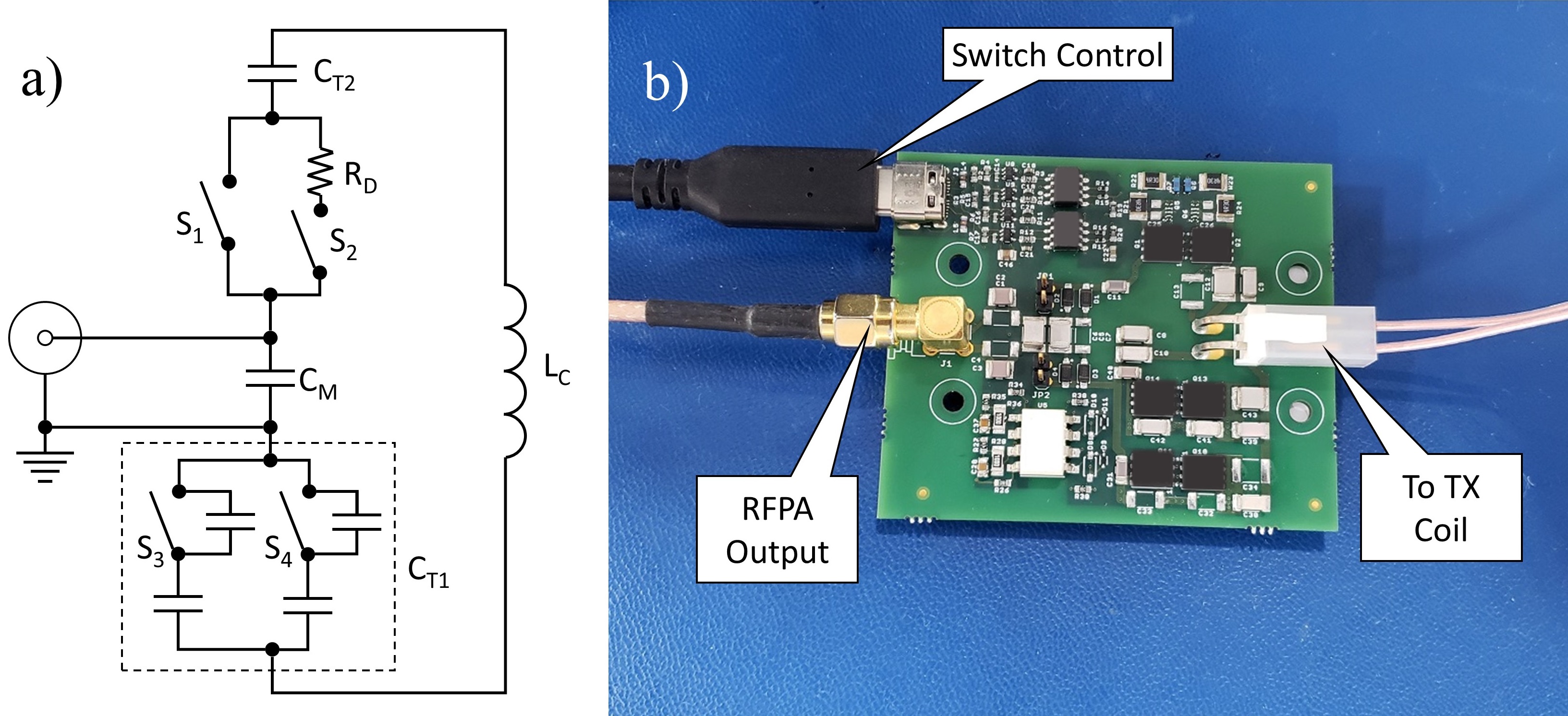
Figure 2a) Block diagram of the
prototype feedboard. The switching circuitry is integrated into the coil’s impedance
matching network. The coil tune capacitor is split into CT1 and CT2.
CT1 comprises fixed capacitors and switches S3 and S4,
allowing the tune frequency to be adjusted. b) Photograph of the prototype
feedboard.
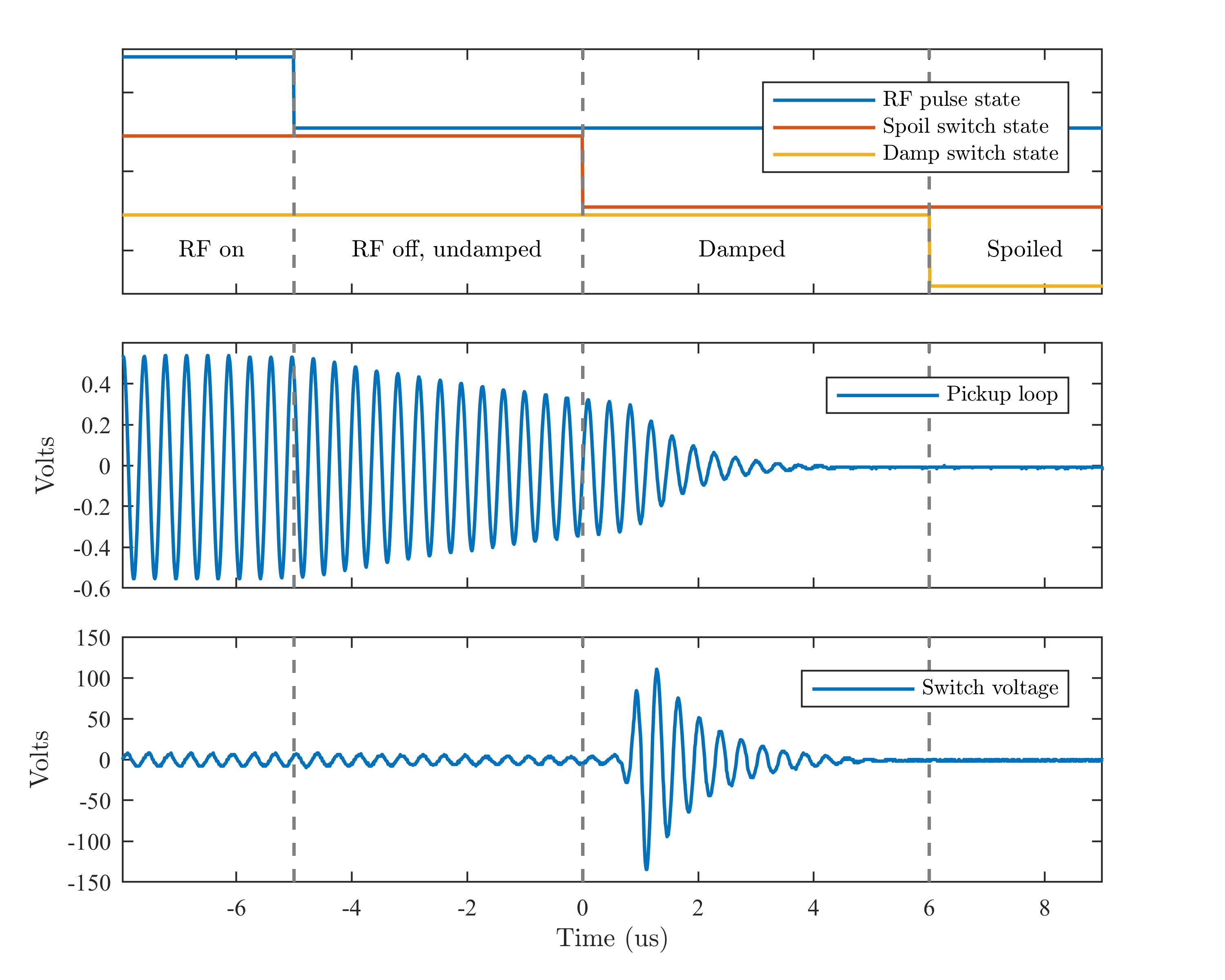
Figure 3) Measured waveforms at the end of
a 200W hard pulse. A) shows the sates of the RF pulse and the two switches. B)
Shows the voltage from a pickup loop coupled to the coil. C) is the voltage
across S1, measured with a high voltage differential probe.