Can Wu1,2 and Qi Peng3
1Department of Medical Physics, Memorial Sloan Kettering Cancer Center, New York, NY, United States, 2Philips Healthcare, Andover, MA, United States, 3Department of Radiology, Albert Einstein College of Medicine and Montefiore Medical Center, Bronx, NY, United States
1Department of Medical Physics, Memorial Sloan Kettering Cancer Center, New York, NY, United States, 2Philips Healthcare, Andover, MA, United States, 3Department of Radiology, Albert Einstein College of Medicine and Montefiore Medical Center, Bronx, NY, United States
3D MAPSS T1ρ mapping with
adiabatic RF pulses is less sensitive to frequency offset compared to
conventional 3D MAPSS T1ρ mapping with continuous-wave RF pulses, potentially
leading to more accurate T1ρ quantification in the presence of field
inhomogeneities.
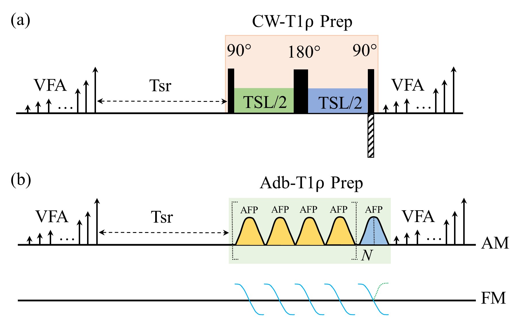
Figure 1. (a). CW-T1ρ preparation is implemented by a
composite RF pulse (90°-TSL/2-180°-TSL/2-90°).
Phase cycling of CW-T1ρ is achieved by a phase
reversal of the last 90° pulse. (b). Adb-T1ρ is achieved by a series of four
adiabatic full passage (AFP) pulse group following MLEV phase cycling. The
frequency modulation of the second half of the last AFP pulse is reversed for phase
cycling. N: number of repeats of the four AFP pulse group; VFA: variable
flip angle; TSL: time of spin lock, Tsr: time for saturation recovery. AM:
amplitude modulation; FM: frequency modulation.
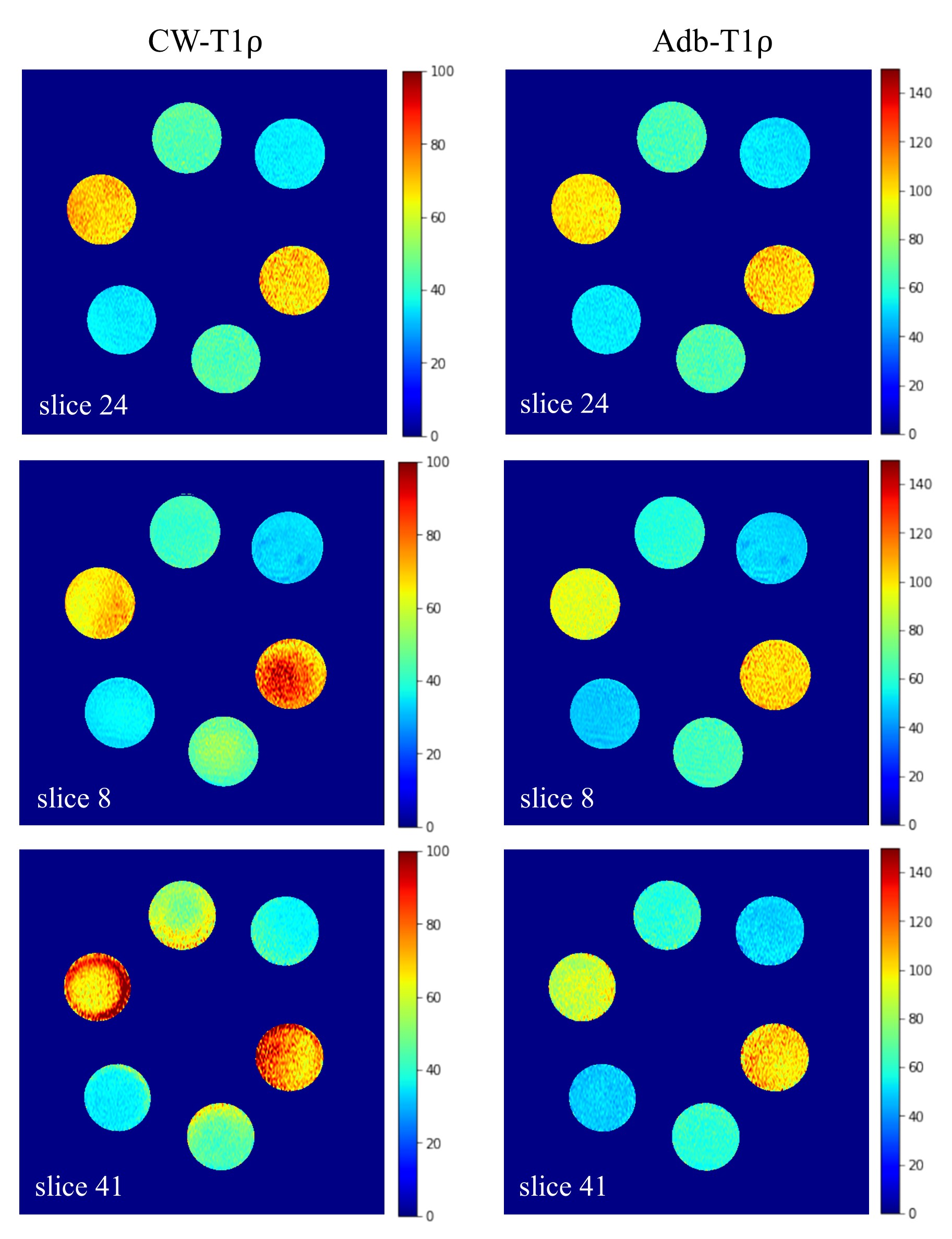
Figure 2.
Example phantom T1ρ maps from 3D MAPSS CW-T1ρ
(left) and Adb-T1ρ (right) at the center slice 24 (top row), off-center slice 8
(middle row) and off-center slice 41 (bottom row). Slice 8 and slice 41 of CW-T1ρ clearly
show non-uniform T1ρ maps due to artifacts from frequency offset, while the T1ρ
maps from Adb-T1ρ are more uniform and consistent at the two off-center slices. CW-T1ρ:
continuous-wave T1ρ mapping; Adb-T1ρ: adiabatic T1ρ mapping.