Myung Kyun Woo1, Lance DelaBarre1, Russell Lagore1, Steve Jungst1, Michael T Lanagan2, Thane Bonnett2, Qing X Yang2, Riccardo Lattanzi3, Kamil Ugurbil1, and Gregor Adriany1
1Center for Magnetic Resonance Research, Minneapolis, MN, United States, 2Penn state University, Centre County, PA, United States, 3Radiology at NYU Grossman School of Medicine, New York University, New York, NY, United States
1Center for Magnetic Resonance Research, Minneapolis, MN, United States, 2Penn state University, Centre County, PA, United States, 3Radiology at NYU Grossman School of Medicine, New York University, New York, NY, United States
Improved
peripheral SNR was achieved for dipole antenna arrays with high dielectric
constant (HDC) materials positioned away from the sample for UHF applications.
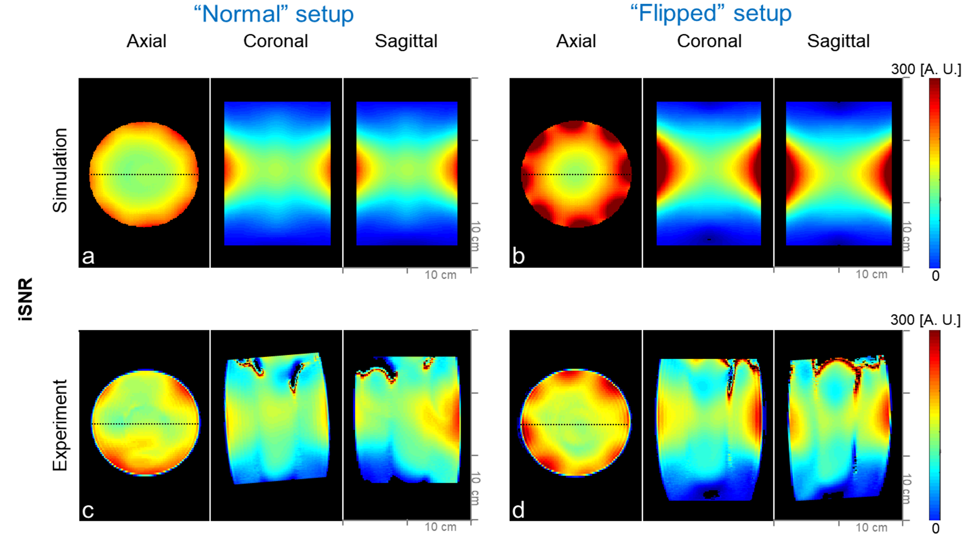
Fig. 4 Simulation
(a and b) and experimental (c and d) iSNR maps of the 8-channel HDC dipole
antenna array of the “Normal” and “Flipped” setups.
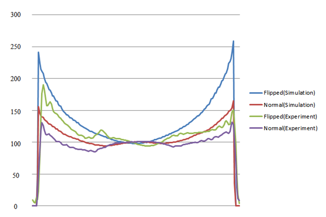
Fig. 5. Profile of the simulated (Blue, Red) and measured
(Green , Purple) iSNR for Flipped and Normal setups. The location of the profiles is indicated as black dotted lines in
Fig. 4 .