Koray Ertan1,2, Trevor Wade3,4, Andrew Alejski4, Charles A McKenzie3, Paolo Decuzzi2, Brian Rutt1, and Peter B Roemer5
1Department of Radiology, Stanford University, Stanford, CA, United States, 2Laboratory of Nanotechnology for Precision Medicine, Italian Institute of Technology, Genoa, Italy, 3Department of Medical Biophysics, Western University, London, ON, Canada, 4Robarts Research Institute, Western University, London, ON, Canada, 5Roemer Consulting, Lutz, FL, United States
1Department of Radiology, Stanford University, Stanford, CA, United States, 2Laboratory of Nanotechnology for Precision Medicine, Italian Institute of Technology, Genoa, Italy, 3Department of Medical Biophysics, Western University, London, ON, Canada, 4Robarts Research Institute, Western University, London, ON, Canada, 5Roemer Consulting, Lutz, FL, United States
Our new methods allowed calculation of E-field
distributions on realistically sized body models with uniform interior; these
were then used to predict population-mean PNS thresholds for widely different
gradient coils with high accuracy. These new tools enable PNS-optimal gradient
design.
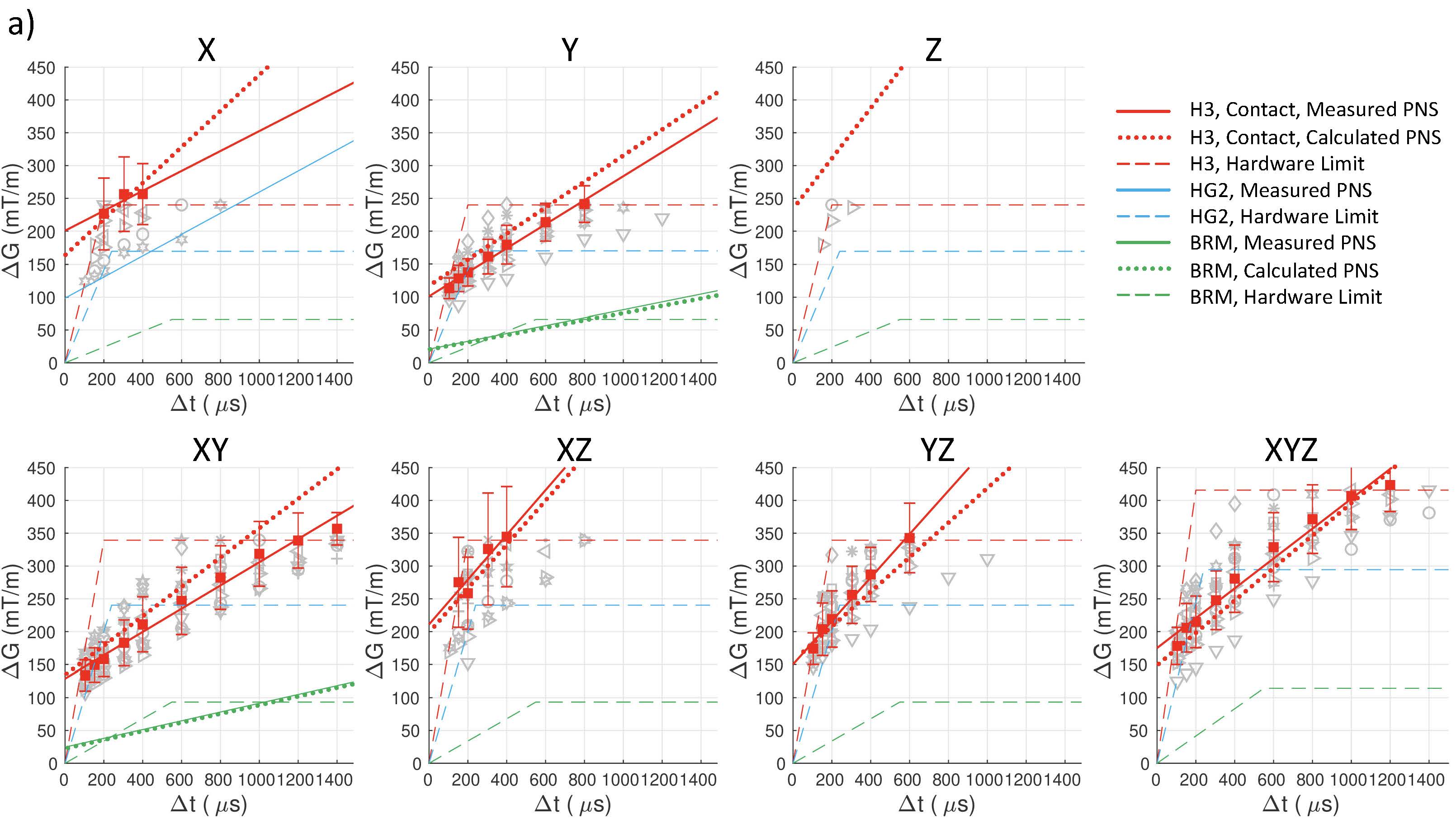
Figure 3: Measured and calculated PNS thresholds as
well as hardware limits for seven gradient directions of H3, shoulder-coil
contact body position. Individual PNS threshold measurements are shown using
open markers. Logistic regression mean experimental PNS values are shown with
solid (filled) markers and error bars. Linear fit to measured PNS thresholds
are shown as solid lines. Hardware limits are shown as dashed lines. Calculated
PNS thresholds shown as dotted lines. Chronaxie value of 600 µs was used for
the head gradient calculations. Vertical axes represent peak to peak ΔG.
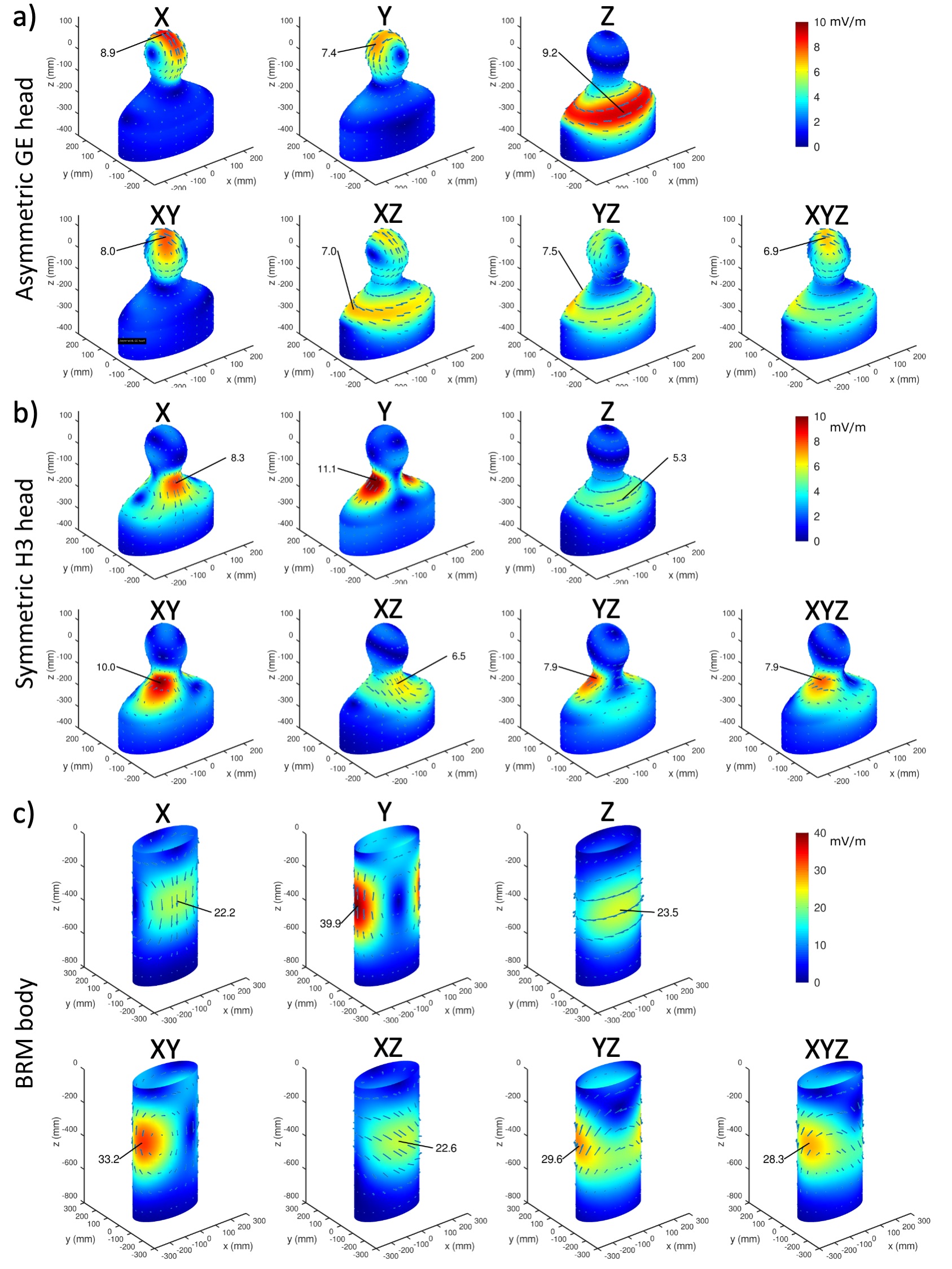
Figure 2: Calculated
E-fields per unit slew rate on the surface of 50th percentile male body
model for (a) asymmetric GE head
gradient, (b) symmetric H3 head gradient (in contact with shoulder) and 40 x 20
cm elliptical cylinder for (c) BRM body gradient coil. E-field directions and
peak E-field value are shown. Only negative Z coordinates for BRM coil are
shown due to symmetry. Peak E-fields
occur at the face and top of the head for X and Y gradients of the asymmetric
GE coil, R/L side of the neck and shoulder region for the Y gradient of H3 and
R/L side of the torso for the BRM coil.