Xinqiang Yan1,2
1Vanderbilt University Institute of Imaging Science, Nashville, TN, United States, 2Department of Radiology and Radilogical Science, Vanderbilt University Medical Center, Nashville, TN, United States
1Vanderbilt University Institute of Imaging Science, Nashville, TN, United States, 2Department of Radiology and Radilogical Science, Vanderbilt University Medical Center, Nashville, TN, United States
“RF transparent” local B0 shim coil have minimal crosstalk
with RF coils without using massive bulky RF chokes.
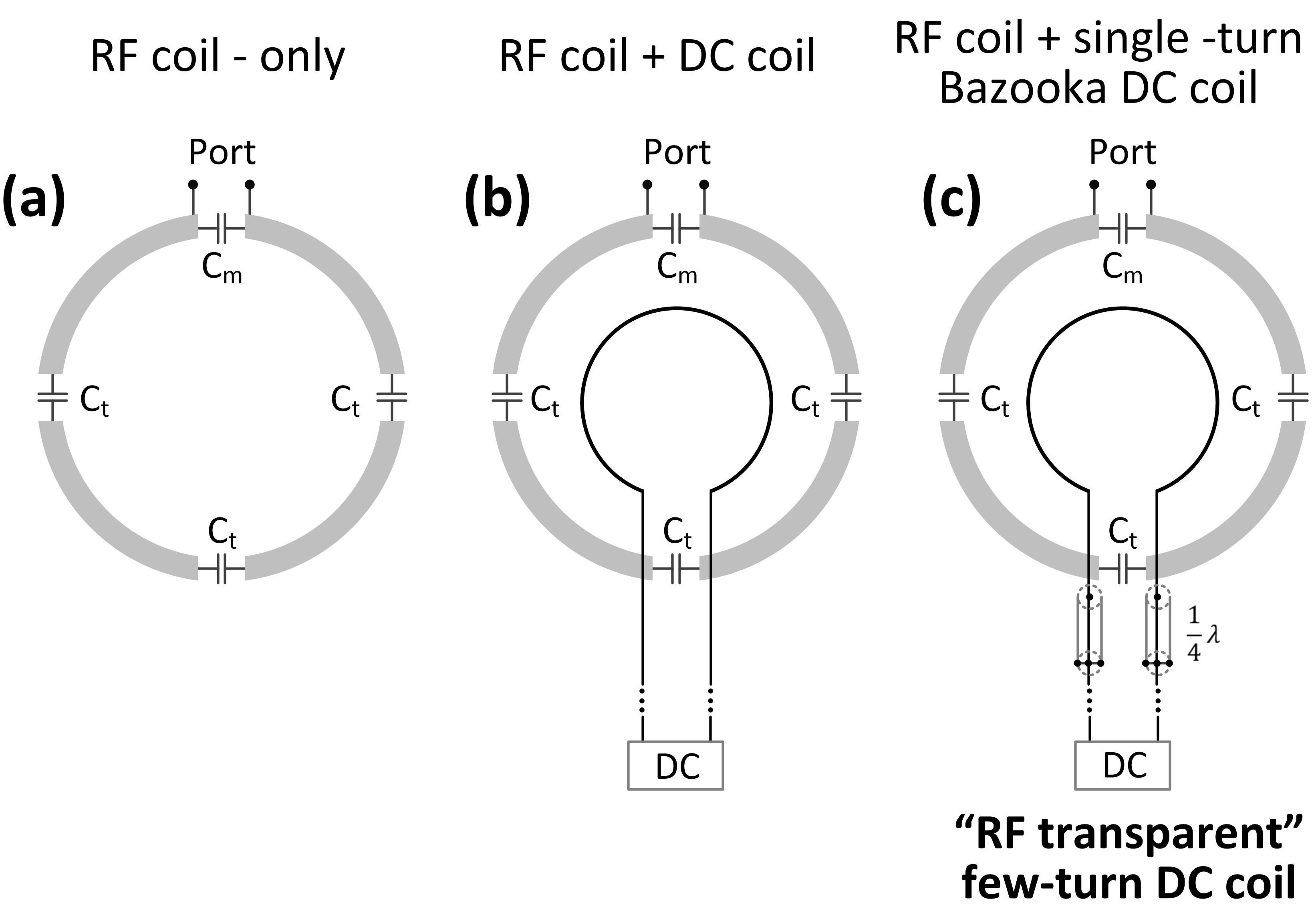
Figure
1 Circuit diagrams of RF-only
coil, RF coil + DC coil, and RF coil + “RF transparent” DC coil. Note that in practice, feed wires of DC coils are typically twisted to cancel the
Lorentz force. For simplicity, straight feed wires were shown here. For Bazooka-feedline [5] few-turn “RF transparent” DC coil, the shield of twisted wires (could be one
shield for each wire or one shield for both wires) was shorted at the position
that is 1/4 wavelength away from the DC coil, forming open circuits and block
RF signal going through.
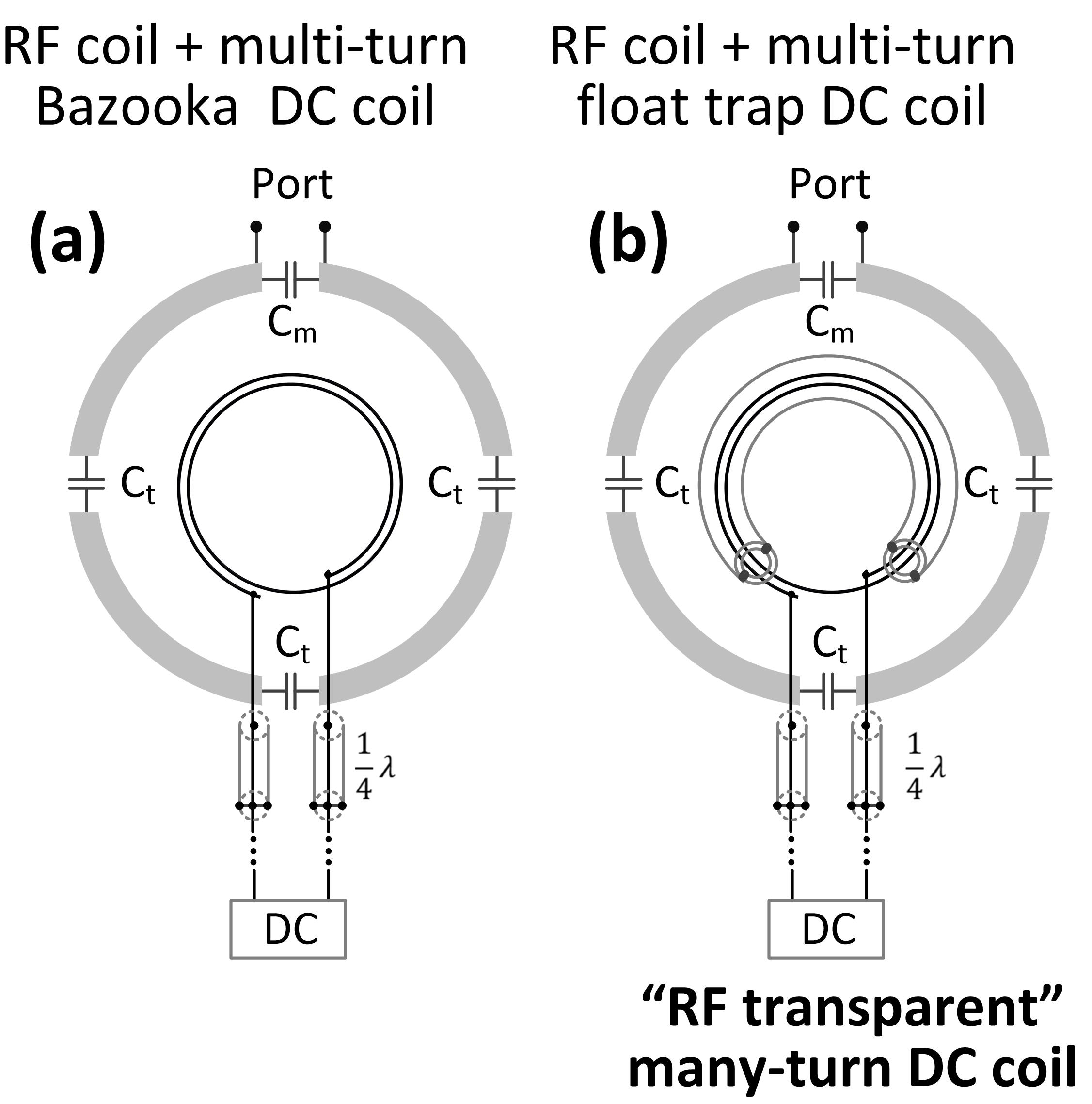
Figure
2 Circuit diagrams of many-turn
“RF transparent” DC coil using float trap design. For many-turn DC coil, it
may resonate close to the RF frequency even the feed port is broken using
the bazooka feedline method (A). In this case, it still can be seen as a
coupled lossy resonator and leads to SNR loss.
The float trap [6] is a concentric resonator that inductively couples and traps
the RF signal going through it. It is expected to break every turn of the DC coil that goes
through the trap and thus avoid unwanted resonate modes.
