Paul Chang1, Sahar Nassirpour1, Kaizad Rustomji2, Elodie Georget2, Ingmar Voogt3, Aidin Haghnejad3, Evita Wiegers4, Jannie Wijnen4, and Dennis Klomp4
1MR Shim GmbH, Reutlingen, Germany, 2Multiwave Imaging, Marseille, France, 3WaveTronica, Utrecht, Netherlands, 4UMC Utrecht, Utrecht, Netherlands
1MR Shim GmbH, Reutlingen, Germany, 2Multiwave Imaging, Marseille, France, 3WaveTronica, Utrecht, Netherlands, 4UMC Utrecht, Utrecht, Netherlands
To minimize RF interference, the Rx loops should be larger than shim coils with an optimal gap of 4cm. An optimized distribution of the shim loops tailored to the brain anatomy achieved significant B0 shimming improvement (43% compared to 2nd order) with at max 1.2dB loss in MR sensitivity.
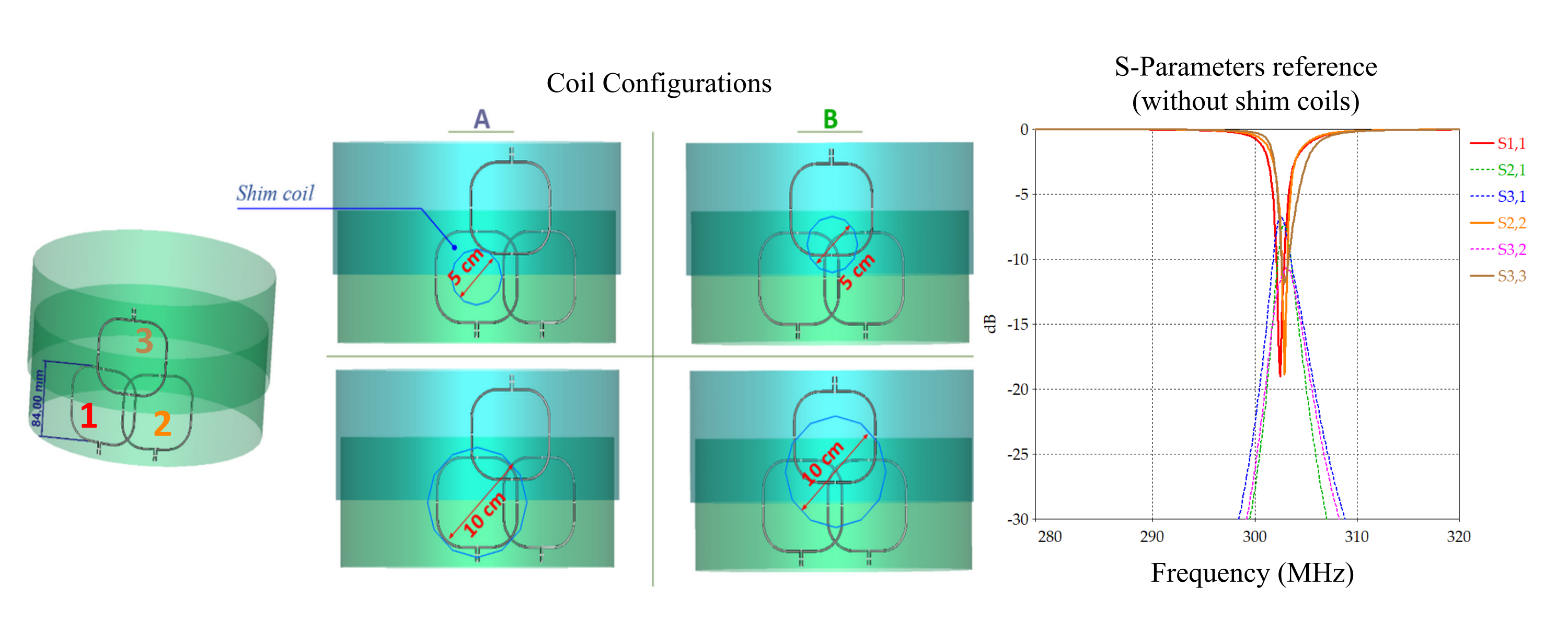
Figure 1 Three RF loops (84mm diameter each) were arranged in the configuration shown on the left. The four different settings for the shim coildiameter/positioning used in the numerical simulation are also shown. The reference S-parameter curves (in the absence of the shim coils) are shown on theright.
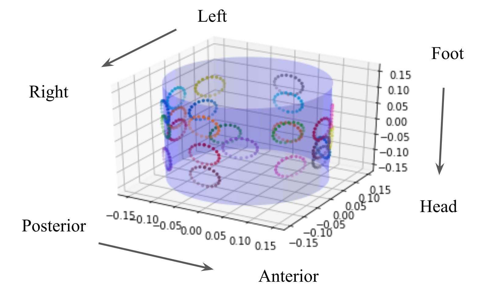
Figure 4 Optimal arrangement of 24 shim coils on a cylindrical holder (units in [m]).