Yonghyun Ha1, Kartiga Selvaganesan1, Baosong Wu1, Kasey Hancock1, Charles Rogers III1, Sajad Hosseinnezhadian1, Gigi Galiana1, and R. Todd Constable1
1Department of Radiology and Biomedical Imaging, Yale School of Medicine, New Haven, CT, United States
1Department of Radiology and Biomedical Imaging, Yale School of Medicine, New Haven, CT, United States
Compensation pulses are shown that were optimized using a series of square
pulses. The SNRs of
the echo signal acquired using compensated pulse was compared with those of
signal obtained with uncompensated pulses and showed significant improvements
of 51.5%.
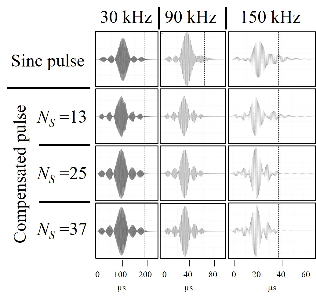
Figure 4. Measured actual pulses (vertical dashed lines indicate the input pulse ends.) of the sinc pulses (top row) and compensated sinc pulses calculated with NS values of 13 (second row), 25 (third row), 37 (bottom row) and bandwidths of 30 kHz (left column), 90 kHz (middle column), and 150 kHz (right column).
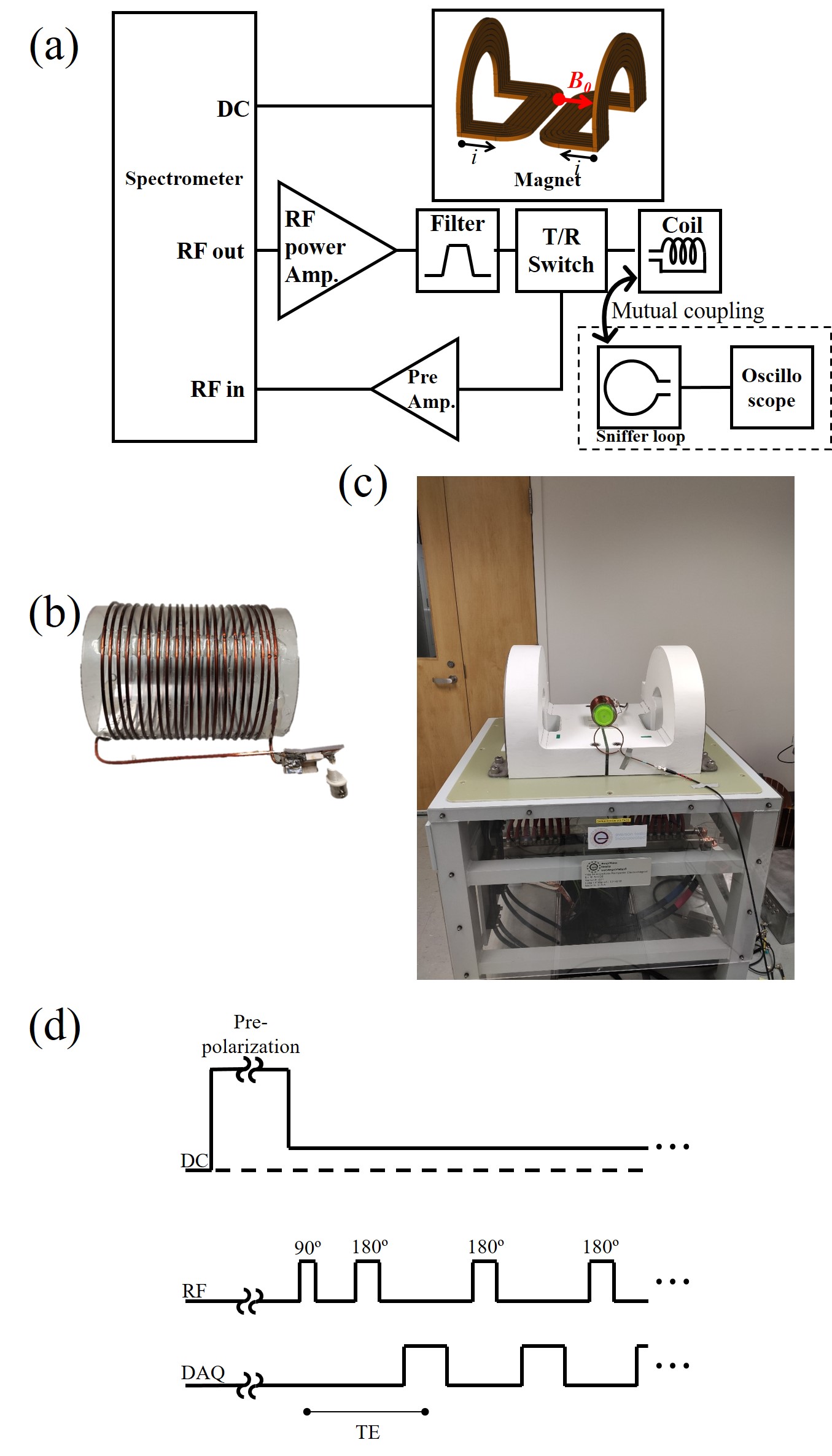
Figure 2. (a) Schematic diagram of an open, table-top, MRI system with photos of (b) the RF solenoid coil and (c) the magnet. (d) A spin-echo sequence with pre-polarization.