Stephen E Russek1, Kathryn E Keenan1, Karl F Stupic1, Teryn S Wilkes2, Ramesh Karki3, and Todor Karaulanov4
1NIST, Boulder, CO, United States, 2Intermountain Neuroimaging Consortium, University of Colorado, Boulder, CO, United States, 3University of Colorado Anschutz, Radiological Sciences, Aurora, CO, United States, 4CaliberMRI, Inc., Boulder, CO, United States
1NIST, Boulder, CO, United States, 2Intermountain Neuroimaging Consortium, University of Colorado, Boulder, CO, United States, 3University of Colorado Anschutz, Radiological Sciences, Aurora, CO, United States, 4CaliberMRI, Inc., Boulder, CO, United States
MRI
System Phantom: Demonstrated MR-readable thermometer for temperature corrections,
geometric distortion analysis down to 1 part in 1000, and fill-conductivity
effects on MR measurements
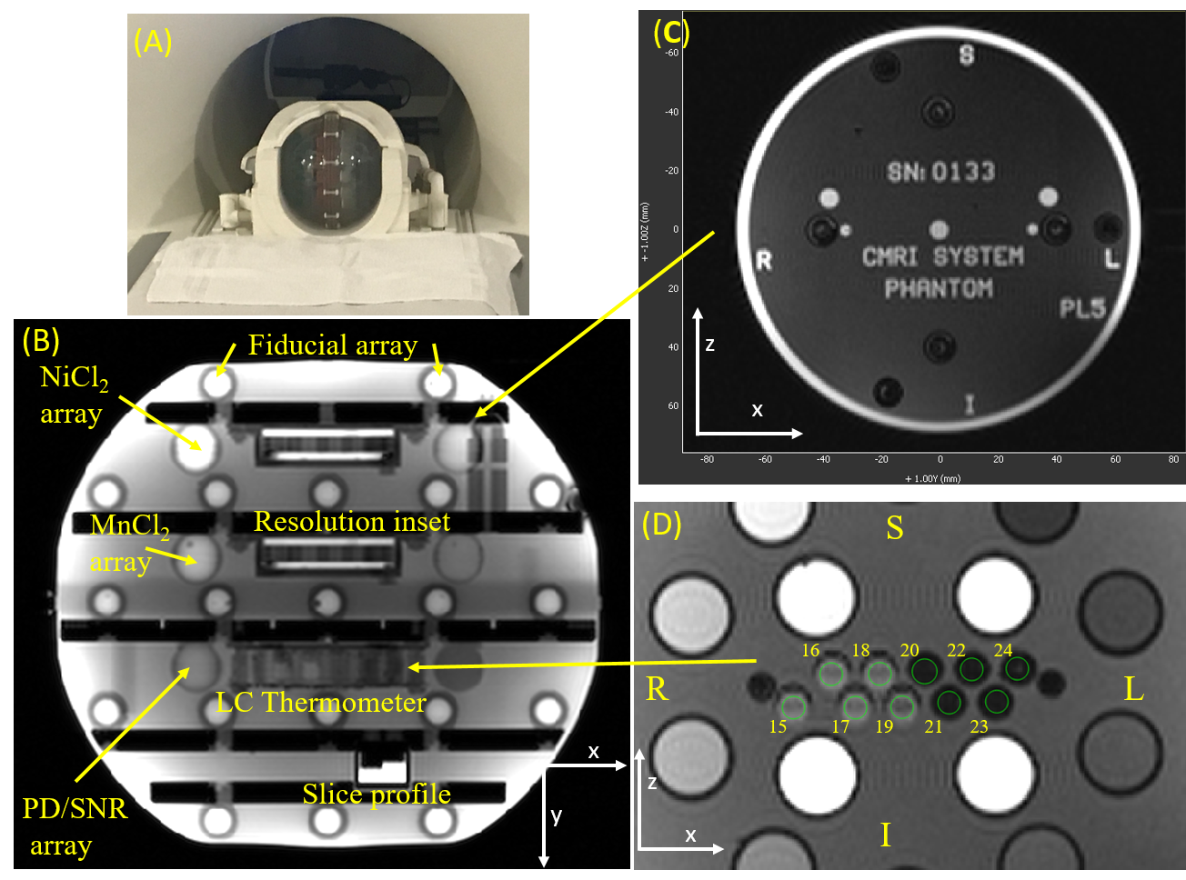
Figure 1. (A) Photo of the system phantom in the 32-channel
head coil, (B) Axial slice showing the phantom plates; fiducial, relaxation
time, and proton density/ signal-to-noise ratio arrays; resolution and slice profile
insets; and the LC thermometer. (C) Top plate of the phantom showing the serial
number and phantom orientation. Here, since the phantom is rotated from its
default orientation right/left (R/L) corresponds to anterior/posterior (A/P) directions for a human in the head
coil. (D) Image of LC thermometer with 4mm regions of interest and transition temperatures
marked.
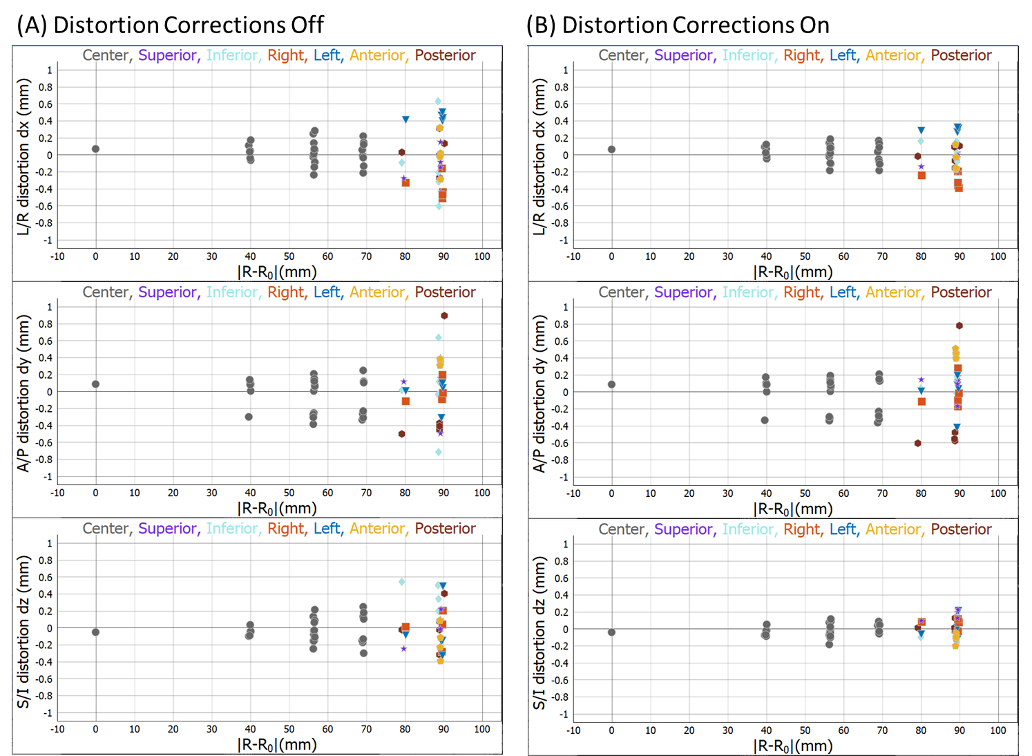
Figure 3. Geometric distortion
data showing the difference of the apparent position of each fiducial sphere from
the real position, as a function of distance from phantom center. (A), (B) distortions with software corrections
turned off and turned on, respectively. The points are color coded to indicate
where they are in the phantom.