Andrea Capozzi1, Jan Kilund2, Magnus Karlsson2, Mathilde Hauge Lerche2, and Jan Henrik Ardenkjær-Larsen2
1LIFMET, EPFL, Lausanne, Switzerland, 2Health Technology, Technical University of Denmark, Kgs. Lyngby, Denmark
1LIFMET, EPFL, Lausanne, Switzerland, 2Health Technology, Technical University of Denmark, Kgs. Lyngby, Denmark
The future of hyperpolarized 13C MRI is to make hyperpolarization transportable. Herein, we demonstrated it for the first time in the case of glucose. We just made a step towards how clinical examinations are performed with PET using the glucose analog 18FDG.
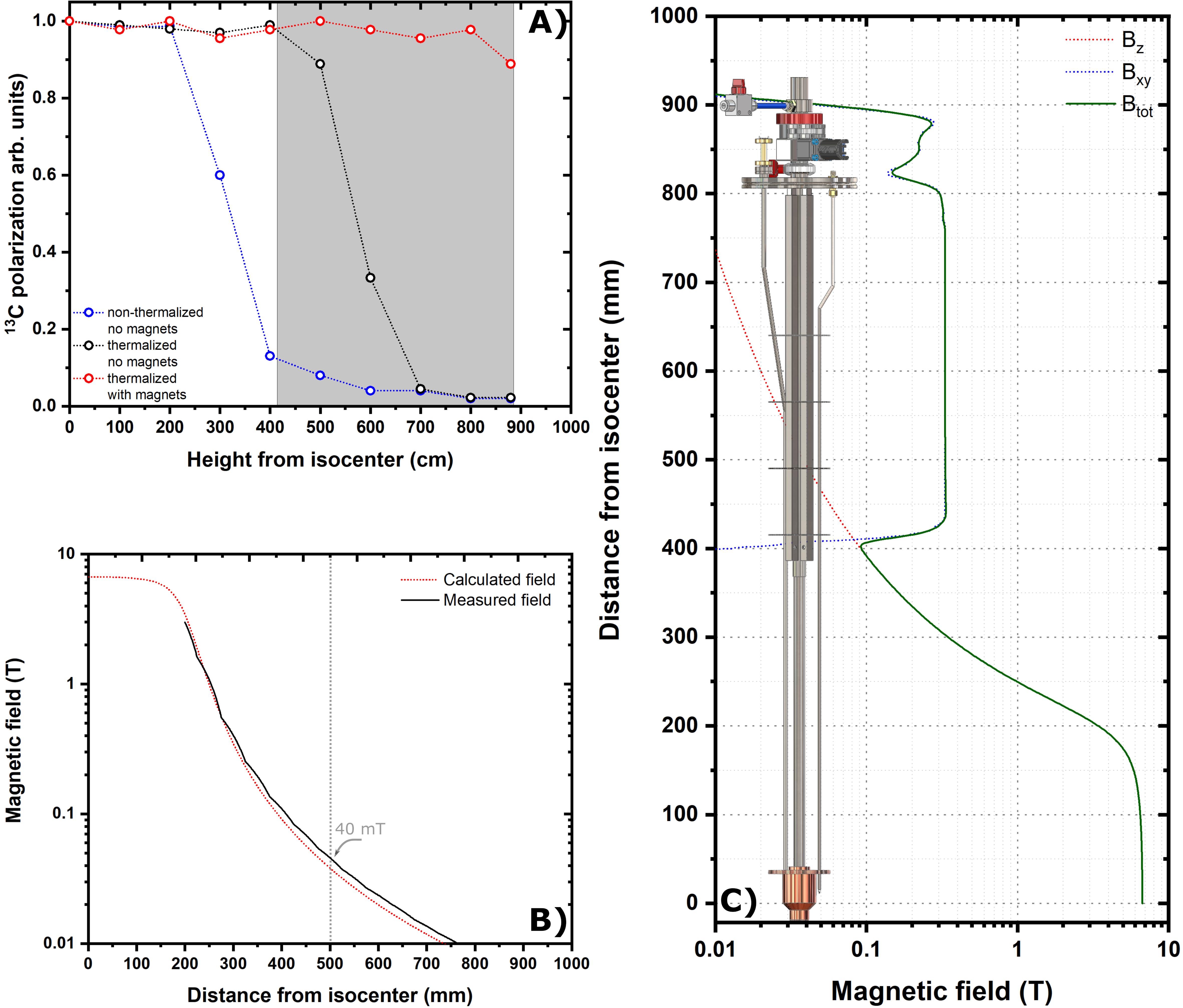
(A) 13C polarization losses as a function of the sample vertical position
inside the polarizer while using a traditional DNP probe (blue and black
circles) and our new probe containing permanent magnets (red circles).The gray shaded area represents
the area covered by permanent magnets in the new probe. (B) Measured (black line) and calculated (red line) polarizer magnetic field profile. (C) Calculated total (green line) magnetic field: superconductive magnet (red dotted line) + permanent magnets (blue dotted line).
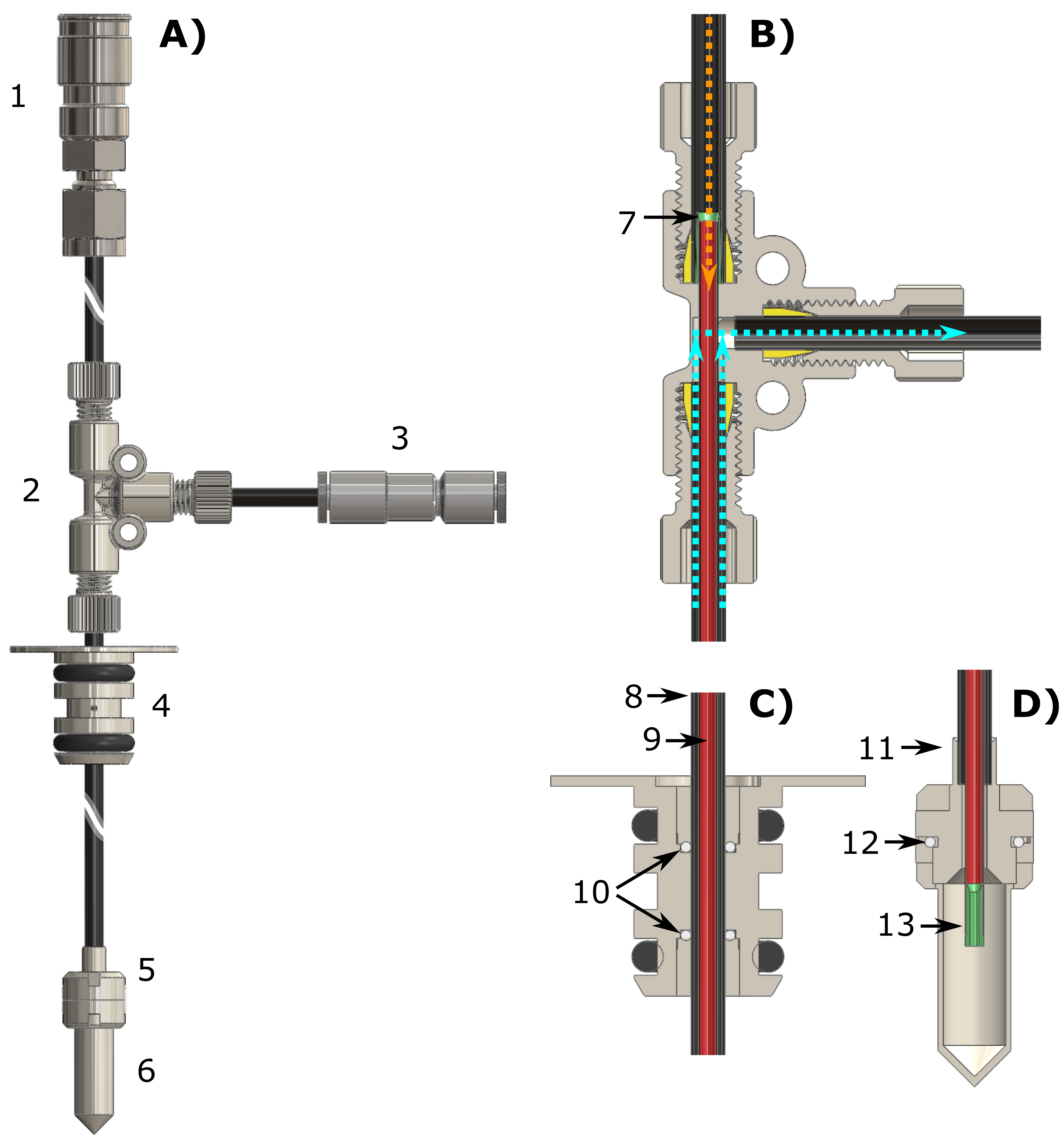
Technical
drawings of the CFP (A) and zoomed section of the T-valve indicating
inner (orange arrow) and outer (cyan arrows) flow directions (B),
dynamic sealing (C) and sample threaded vial (D). Numbers
indicates the most important components of the device: quick release connection
(1), T-valve (2), one-way valve (3), dynamic sealing (4), vial top part (5),
vial bottom part (6), outer-lumen to inner-lumen transition (7), black PEEK
outer-lumen (8), red PEEK inner-lumen (9), dynamic sealing silicone o-ring (10),
laser welded joint (11), vial PTFE o-ring (12), nozzle (13).