Jürgen Herrler1, Patrick Liebig2, Rene Gumbrecht2, Sydney Nicole Williams3, Christian Meixner4, Andreas Maier5, Arnd Dörfler1, and Armin Michael Nagel4
1Institue of Neuroradiology, University Hospital Erlangen, Erlangen, Germany, 2SIEMENS Healthineers, Erlangen, Germany, 3Imaging Centre of Excellence, University of Glasgow, Glasgow, Scotland, 4Institue of Radiology, University Hospital Erlangen, Erlangen, Germany, 5Friedrich Alexander University Erlangen Nürnberg, Erlangen, Germany
1Institue of Neuroradiology, University Hospital Erlangen, Erlangen, Germany, 2SIEMENS Healthineers, Erlangen, Germany, 3Imaging Centre of Excellence, University of Glasgow, Glasgow, Scotland, 4Institue of Radiology, University Hospital Erlangen, Erlangen, Germany, 5Friedrich Alexander University Erlangen Nürnberg, Erlangen, Germany
A universal parallel transmit (pTx) pulse was used in a B0 mapping sequence. This lead to different values in the resulting B0 maps, mainly at tissue interfaces. When used for the design of a pTx inversion pulse, these differences lead to reduced B0 artifacts in the corresponding sequence.
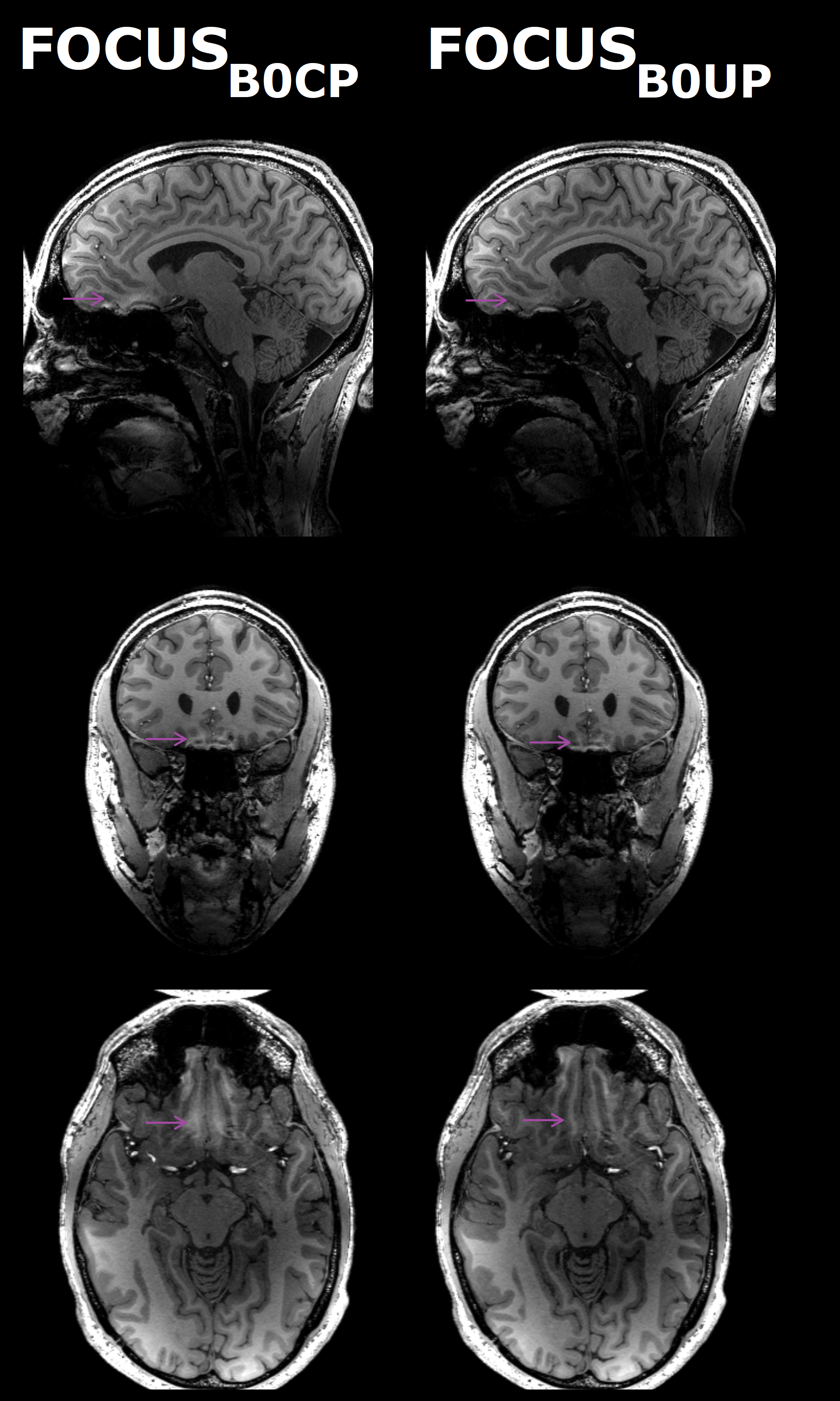
Figure 4 MPRAGE images using
FOCUS pTx pulses, based on B0 maps, which were acquired with either
a CP pulse or a UP. The purple arrows indicate B0 related artifacts,
which were weakened when using the UP-improved B0 mapping for designing the pTx inversion pulse. Different
behavior of the excitation pulses could not be observed.
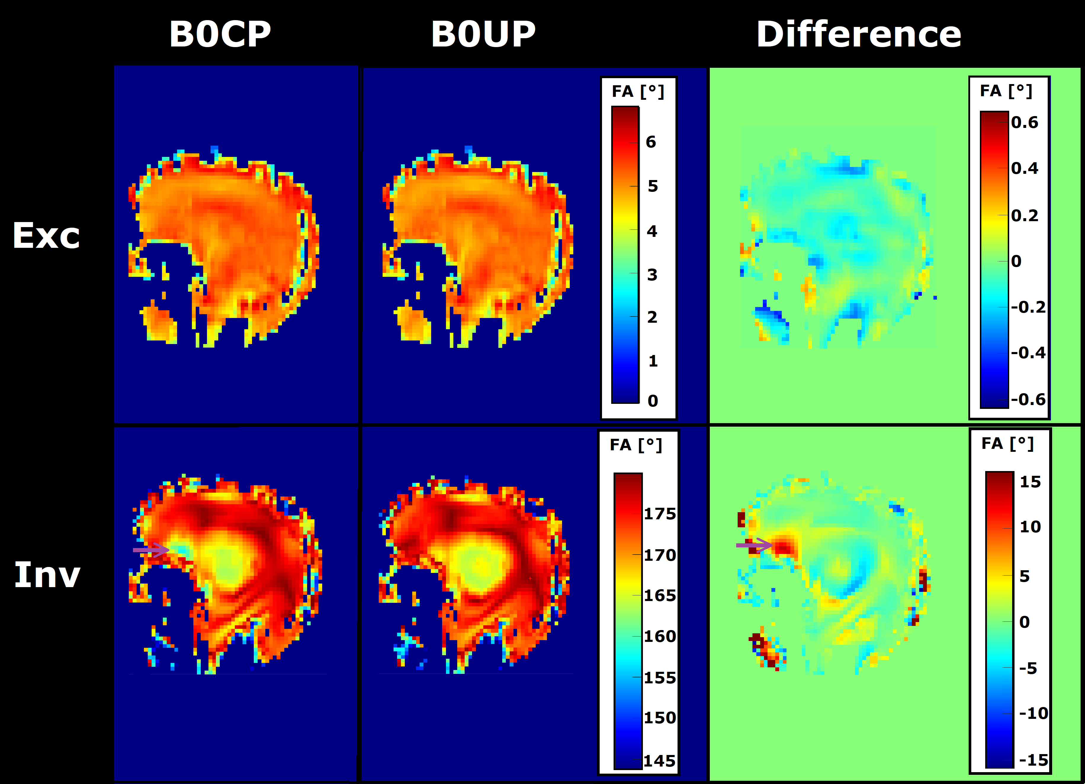
Figure 3 FA simulations of FOCUS
excitation (Exc) and inversion (Inv) pulses using either the B0 map
acquired with a CP pulse (B0CP) or a UP (B0UP), as well as the difference maps
(‘UP case – CP case’). All Bloch simulations were performed using the B0
map acquired with the UP. B0 maps acquired with CP pulses may lead
to a worse performance of the FOCUS inversion pulse, especially in the sinus region (purple
arrow).