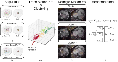
-
Prospective motion-corrected three-dimensional multiparametric mapping of the brain
Shohei Fujita1,2, Naoyuki Takei3, Akifumi Hagiwara1, Issei Fukunaga1, Dan Rettmann4, Suchandrima Banerjee5, Ken-Pin Hwang6, Shiori Amemiya2, Koji Kamagata1, Osamu Abe2, and Shigeki Aoki1
1Department of Radiology, Juntendo University, Tokyo, Japan, 2Department of Radiology, The University of Tokyo, Tokyo, Japan, 3MR Applications and Workflow, GE Healthcare, Tokyo, Japan, 4MR Applications and Workflow, GE Healthcare, Rochester, MN, United States, 5MR Applications and Workflow, GE Healthcare, Menlo Park, CA, United States, 6Department of Radiology, MD Anderson Cancer Center, Houston, TX, United States
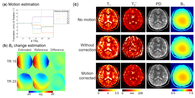
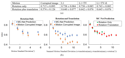
High linearity of T1 and T2 values in a phantom was obtained with and without motion correction. The repeatability and accuracy of T1 and T2 quantification were improved under in-plane and through-plane motions.
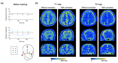
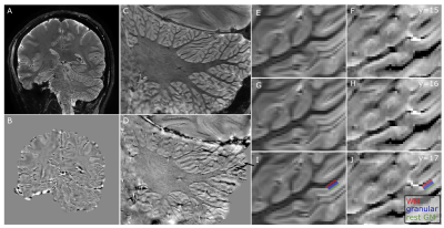
Figure 3. Representative motion tracking and quantitative maps of a healthy volunteer with intentional in-plane (“side-to-side”) head motions. The head motion was rigidly tracked in three translational and three rotational directions. (a) Motion tracking time curve of translations and rotations in the x-y-z coordinate system. (b) T1 and T2 maps acquired with the proposed method and those without motion correction are shown.
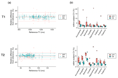
Figure 5. Effect of motion correction on regional quantitative values. (a) Bland-Altman plots representing the bias of scans with motion with and without motion correction compared with scans without motion as references. Data points with motion correction are closer to zero than those without, indicating smaller bias achieved by motion correction. (b) Coefficients of variation (CV) represent the repeatability of the scans. In both T1 and T2, within-subject CVs were smaller, indicating higher repeatability, in motion-corrected scans than those without motion correction.
-
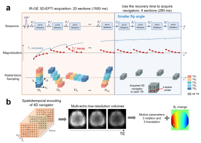
3D rigid motion correction for navigated interleaved simultaneous multi-slice DWI
Malte Riedel (né Steinhoff)1, Kawin Setsompop2,3,4, Alfred Mertins1, and Peter Börnert5,6
1Institute for Signal Processing, University of Lübeck, Lübeck, Germany, 2Athinoula A. Martinos Center for Biomedical Imaging, Charlestown, MA, United States, 3Department of Radiology, Harvard Medical School, Boston, MA, United States, 4Harvard‐MIT Health Sciences and Technology, MIT, Cambridge, MA, United States, 5Philips Research, Hamburg, Germany, 6Department of Radiology, C.J. Gorter Center for High-Field MRI, Leiden University Medical Center, Leiden, Netherlands
The
proposed method offers navigated retrospective 3D rigid motion correction per
EPI-shot for interleaved SMS brain DWI. Simulations
confirm small submillimeter target registration errors.
In-vivo
DTI results show improved image quality at a high temporal resolution of 3 Hz.
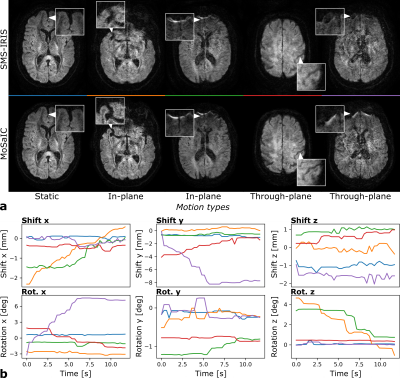
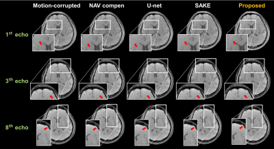
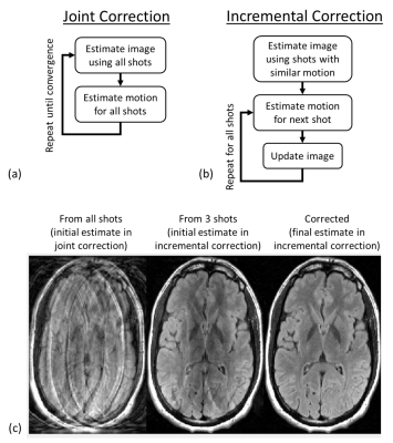
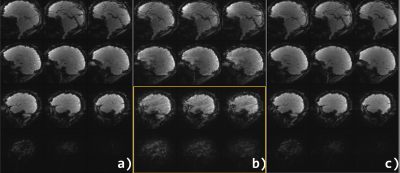
Figure 4: In-vivo examples from 4-interleave 3-SMS
full-volume DWI reconstructions. a: SMS-IRIS
and MoSaIC examples. b: Shot-wise shift and rotation parameters for MoSaIC (see
color code). In the static case (blue), the parameters are almost constant and
the images appear similar. The SMS-IRIS images of the next two examples (orange
and green) are visibly blurred by in-plane motion, which is improved by MoSaIC.
The last two SMS-IRIS images (red and purple) are mainly affected by
through-plane motion, which is detected as x-rotations and y-shifts and
improved by MoSaIC.
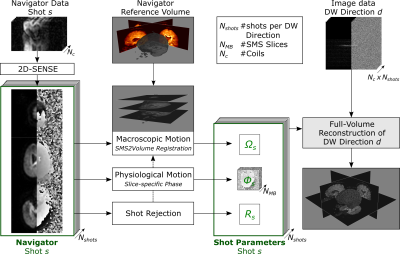
Figure 1: MoSaIC
scheme for navigated DWI reconstruction per diffusion direction including 3D
rigid motion correction. SMS
navigators are unfolded using 2D-SENSE. The shots from the first
diffusion-weighted TR are assumed motion-free and stacked to the reference
volume. The navigator SMS groups are registered by SMS2Vol registration, the
shot diffusion phases
are extracted and rejection criteria
are
calculated. All shot parameters are included into a motion-corrected
full-volume reconstruction combining the high-resolution image data.
-
Cortical Mapping and T1-Relaxometry using Motion Corrected MPnRAGE: Test-Retest Reliability with and without Motion Correction
Steven Kecskemeti1, Abigail Freeman1, and Andrew L Alexander1
1University of Wisconsin-Madison, Madison, WI, United States
Retrospectively motion corrected MPnRAGE demonstrated high test-retest of R1 relaxometry of the cortex, as well as FreeSurfer measures of cortical thickness, surface area, and volume. High test-retest of pediatric subjects was found with 100% data acceptance.
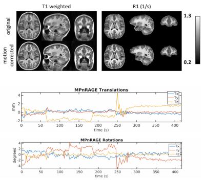
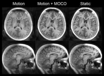
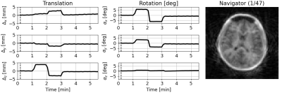
Figure 1: Example images and motion estimations from a 7.6 year old typically developing female demonstrating MPnRAGE motion correction for moderate to severe motions. Without motion correction, the T1-weighted and quantitative R1 images have blurred tissue boundaries.
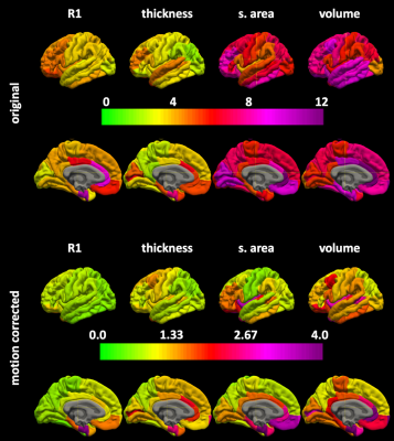
Figure 3. The regional surface maps for the coefficients of variations x 100 without (top) and with (bottom) motion correction.
-
Prospective Motion Corrected Time-of-flight MR Angiography at 3T
Xiaoke Wang1, Edward Herskovits1, and Thomas Ernst1
1Diagnostic Radiology, University of Maryland-Baltimore, Baltimore, MD, United States
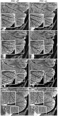
In this study, at 3T field strength MRA with optic PMC was tested in phantom and on a healthy volunteer and compared with MRA without PMC. This study demonstrated the potential of optic PMC in improving the quality of MRA on patients with difficulty holding still.
Figure
5. Axial maximum intensity projections
(MIPs). The MIPs are of very high quality with detailed depiction of distal
vessels and excellent background suppression in the cases of no intentional
motion (A and B). The trained motion causes clear misregistration between
vessels in the brain (C, red arrow). Further, many distal vessels are lost on
the motion corrupted image (C, yellow
arrow), and there are artifactual stenoses (C, green arrow). With prospective
motion correction, the misregistration and the distal vessels are mostly
recovered, and pseudostenosis is
corrected.
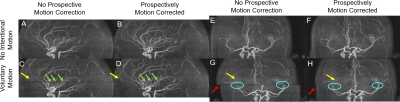
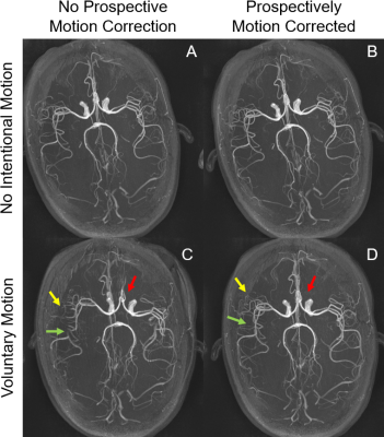
Figure
4. Sagittal (A, B, C, D) and coronal
(E,F,G,H) maximum intensity projections (MIPs). Without intentional motion (A,
B, E, F), activation of PMC does not substantially alter image quality. With
trained motion, some vessels in the middle
slab are obscured (yellow arrows) (C,G) without PMC. There are
artifactual stenoses between slabs (green arrows). There is also misalignment
between slabs (G, red arrow) and discontinuous major vessels, e.g. the middle
cerebral arteries (G). In comparison,
the obscured vessels are recovered when PMC was on and misalignment alleviated (D, H).
-
Dual-echo volumetric navigators for field mapping and shim correction in MR neuroimaging
Alan Chu1, Yulin Chang2, André J. W. van der Kouwe3, and M. Dylan Tisdall1
1Radiology, Perelman School of Medicine, University of Pennsylvania, Philadelphia, PA, United States, 2Siemens Medical Solutions USA, Inc., Malvern, PA, United States, 3Athinoula A. Martinos Center for Biomedical Imaging, Massachusetts General Hospital, Charlestown, MA, United States
We demonstrate the
feasibility and validity of field mapping using a dual-echo vNav based on a
fly-back EPI readout.
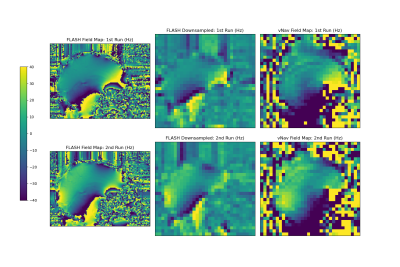
Sagittal field maps
generated from the multi-echo FLASH and dual-echo vNav acquisitions shown in Hz.
The FLASH field maps were downsampled by a factor of 4 to match the resolution
of the vNavs for easier comparison. Note that the field map values have not
been unwrapped, so may not be entirely comparable in regions of very high
susceptibility due to differences in echo timing between the FLASH and vNav
scans.
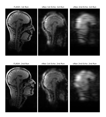
Sagittal views of magnitude
images from the FLASH and vNav scans, for each of the first and second runs. For
the first run, the subject's head was held in a fixed neutral position, and for
the second run, the subject's head was held in a fixed upward nodding position.
-
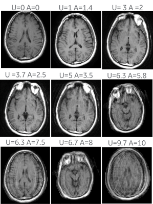
Comprehensive Analysis of FatNav Motion Parameters Estimation Accuracy in 3D Brain Images Acquired at 3T
Elisa Marchetto1,2, Kevin Murphy1,3, and Daniel Gallichan1,2
1Cardiff University Brain Research Imaging Centre (CUBRIC), Cardiff University, Cardiff, United Kingdom, 2School of Engineering, Cardiff University, Cardiff, United Kingdom, 3School of Physics, Cardiff University, Cardiff, United Kingdom
The FatNav motion correction technique
is shown to be able to correct for a large range of motion artifacts, in case
of both smoother and rougher kinds of motion. Even greater robustness is
expected by updating the GRAPPA weights throughout the scan.
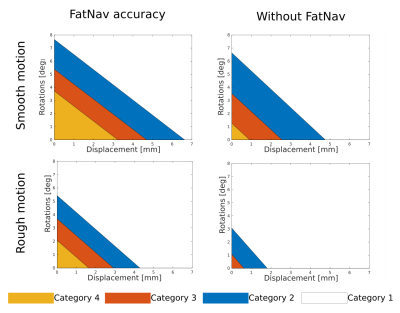
Figure
5. Each coloured region in the plot bounds the rotational and
translational motion parameters range for each evaluation category
after FatNav (left) and without motion correction (right), in case of
smooth (top row) and rough motion (bottom row). FatNavs can correct
very well for an RMS value, averaged along the three axes, of
~3.7°/3mm and 2°/1.6mm for smooth and rough motion respectively
(category 4 boundary); without motion correction, image quality drops
much more quickly (~1.2°/1mm).
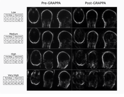
Figure
1. Comparison between FatNav volume before and after GRAPPA
‘re-reconstruction’, for four different amounts of motion (tables
on the left), to simulate effect of mismatched ACS data: parallel
imaging artifacts increase with the amount of motion.
-
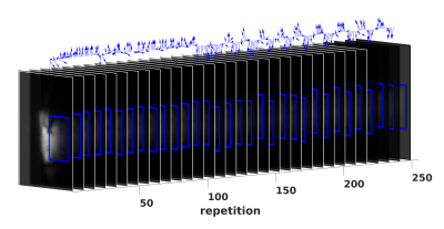
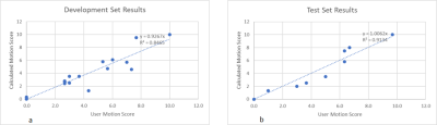
Head Motion Tracking in MRI Using Novel Tiny Wireless Tracking Markers and Projection Signals
Liyuan LIANG1, Chim-Lee Cheung2, Ge Fang2, Justin Di-Lang Ho2, Chun-Jung Juan3,4,5, Hsiao-Wen Chung6, Ka-Wai Kwok2, and Hing-Chiu Chang1
1Department of Diagnostic Radiology, The University of Hong Kong, Hong Kong, Hong Kong, 2Department of Mechanical Engineering, The University of Hong Kong, Hong Kong, Hong Kong, 3Department of Medical Imaging, China Medical University Hsinchu Hospital, Hsinchu, Taiwan, 4Department of Radiology, School of Medicine, College of Medicine, China Medical University, Taichung, Taiwan, 5Department of Medical Imaging, China Medical University Hospital, Taichung, Taiwan, 6Department of Electrical Engineering, National Taiwan University, Taipei, Taiwan
In this study, we evaluated the tracking performance of a novel tiny wireless tracking marker by using a linear motion phantom, and tested the feasibility in omnidirectional 3D head motion tracking using three tiny wireless tracking markers.
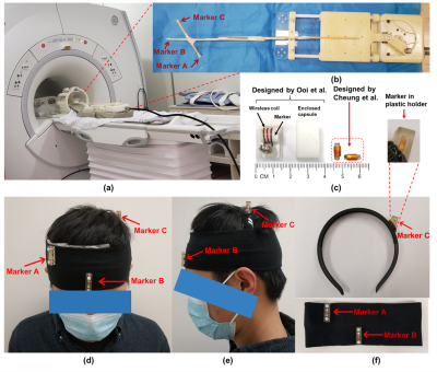
Figure
1. (a) The setup for phantom test. (b) Three markers were stuck on a wooden rod, and then attached on the base plate of the MR motion phantom, which can produce smooth linear
motion. (c) Left: wireless tracking marker proposed in reference [2]; Right:
marker used in our method. (d-f) Demonstration of our homemade head strap. Markers were placed in plastic holders
and then attached on the headbands.
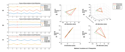
Figure
4. Tracking results of in-vivo experiments. (a-c) Measured tracking traces along
three directions (LR: left-right, SI: superior-inferior, AP: anterior-posterior)
when head shaking was performed. (d-g) Measured positions in 3D space for three
markers at two selected time points (red and green markers in Fig.4a).
-
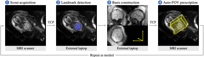
Real-time prospective motion correction of arbitrary MR pulse sequences with XPACE-Pulseq
Maxim Zaitsev1, Michael Woletz1, and Martin Tik1
1High Field MR Center, Center for Medical Physics and Biomedical Engineering, Medical University of Vienna, Vienna, Austria
Prospective
motion correction using external tracking is feasible for arbitrary pulse
sequences stored in Pulseq format.
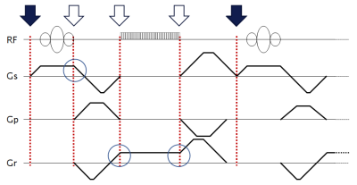
Figure 1. An example of a gradient echo sequence timing diagram. Red
dotted lines mark possible block boundaries. RF pulses and ADC events are not
allowed to cross block boundaries; however, gradients are not forced to 0 at
the boundaries (see blue circles), allowing for efficient gradient wave forms as needed for the
fast sequences. Block arrows on the top mark possible position update points;
filled ones correspond to the currently implemented option.
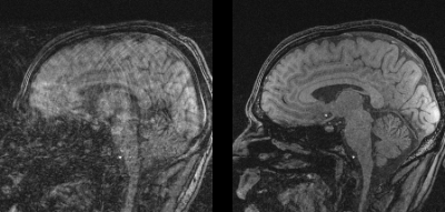
Figure 2. In
vivo images acquired with a 3D gradient echo sequence programmed in Pulseq in presence of head rotations: (left) without prospective motion correction and (right) with prospective motion correction. See Fig. 3 for corresponding motion traces.
-
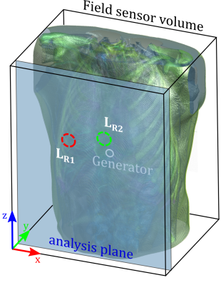
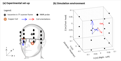
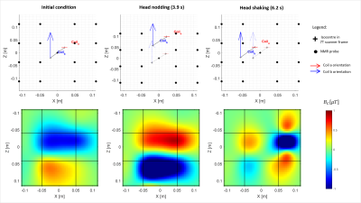
Measuring extracranial magnetic field changes due to head motion during multi-slice EPI acquisition
Laura Bortolotti1 and Richard Bowtell1
1Sir Peter Mansfield Imaging Centre, University of Nottingham, Nottingham, United Kingdom
Head motion parameters were successfully predicted from measurements of extra-cranial field changes made during an EPI
scan.
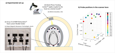
Experimental set-up. The NMR field probes were placed between the transmit and the receiver Rf coils. The optical camera (MPT, Kineticor) is fixed to the inside of the magnet bore. The positions of the probes are shown in (b).
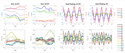
The plots show examples of simultaneous measurements of head motion parameters (top row) and magnetic field (bottom row). The subject performed various head movements (rest, head shaking, head nodding, feet wiggling). Measurements were acquired with and without simultaneous EPI scanning.
-
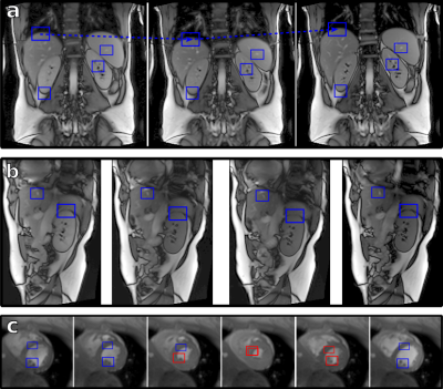
Structure Light based Optical MOtion Tracking system (SLOMO) for Contact-free respiratory Motion Tracking from Neck in MR Imaging
Chunyao Wang1, Zhensen Chen1, Yishi Wang2, and Huijun Chen1
1Center for Biomedical Imaging Research, School of Medicine, Tsinghua University, Beijing, China, 2Philips Healthcare, Beijing, China
This study proposed a parallel
line Structure Light based Optical Motion Tracking system (SLOMO) and verified
its feasibility in respiratory detection and motion correction in MR liver
imaging.
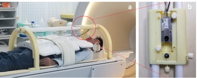
Fig. 1 The setup of SLOMO
system for abdominal imaging. SLOMO system consist of frame holder (a.) and
optical module (b). Optical module is a camera-laser system for depth
imaging
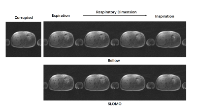
Fig. 4 Reconstruction
results of motion corrupted and corrected images. Liver images were reconstructed
into 4 phases according to the respiratory curves detected by bellow and SLOMO system.
-
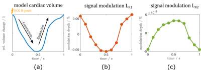
Respiratory resolved and corrected 3D $$$\Delta\text{B0}$$$ mapping and fat-water imaging at 7 Tesla
Sebastian Dietrich1, Johannes Mayer1, Christoph Stephan Aigner1, Christoph Kolbitsch1, Jeanette Schulz-Menger2,3,4, Tobias Schaeffter1,5, and Sebastian Schmitter1,6
1Physikalisch-Technische Bundesanstalt (PTB), Braunschweig and Berin, Germany, 2Charité Medical Faculty University Medicine, Berlin, Germany, 3DZHK partner site Berlin, Working Group on Cardiovascular Magnetic Resonance, Experimental and Clinical Research Center (ECRC), Berlin, Germany, 4Department of Cardiology and Nephrology, HELIOS Klinikum Berlin Buch, Berlin, Germany, 5Department of Medical Engineering, Technische Universität Berlin, Berlin, Germany, 6University of Minnesota, Center for Magnetic Resonance Research, Minneapolis, MN, United States
Respiratory-resolved and corrected 3D $$$\Delta B0$$$ mapping for 3D fat-water separated cardiac magnetic resonance imaging at ultra high fields is presented.
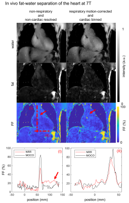
Fig.4: Resulting in vivo
fat-water and fat fraction ($$$\text{FF}$$$) images of a coronal slice are shown for
non-respiratory, non-cardiac resolved (NRR) and respiratory motion-corrected,
cardiac binned (MOCO) reconstruction. The latter is shown in the end-diastolic
phase. The red arrows indicating a blood flow artifact visible in NRR and
reduced in MOCO. Line plot position is indicated by the dotted lines (I) and
(II) with increased $$$\text{FF}$$$ for MOCO up to $$$24\%$$$ and reduced blood flow artifacts by the factor of 2 compared with NRR.
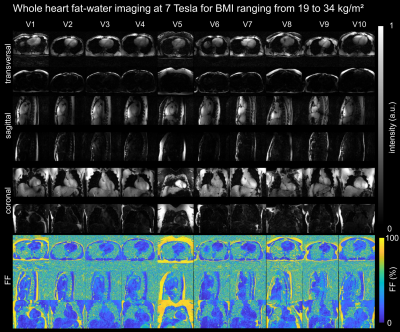
Fig.5: Fat-water and fat
fraction ($$$\text{FF}$$$) images for 3 orthogonal views are shown for all 10 volunteers.
-
Minimizing motion artifacts in myocardial quantitative mapping by combined use of motion-sensitive CINE imaging and FEIR
Takumi Ogawa1, Michinobu Nagao2, Masami Yoneyama3, Yasutomo Katsumata3, Yasuhiro Goto1, Isao Shiina1, Yutaka Hamatani1, Kazuo Kodaira1, Mamoru Takeyama1, Isao Tanaka1, and Shuji Sakai2
1Department of Radiological Services, Women's Medical University Hospital, tokyo, Japan, 2Department of Diagnostic imaging & Nuclear Medicine, Women's Medical University Hospital, tokyo, Japan, 3Philips Japan, tokyo, Japan
The
combined use of Motion-Sensitive (MoSe) CINE imaging for determining accurate
TD setting and fast elastic image registration (FEIR) could minimizing the
influence of cardiac motion-related artifacts.
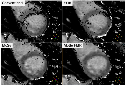
Figure.2 A comparison MOLLI T1mapping with/without MoSe-CINE approach and FEIR. Both
conventional MoSE-CINE visual approach with FEIR clearly improved the accuracy
on T1 confidence map and the combination of MoSE-CINE visual approach with FEIR
showed the best image quality.
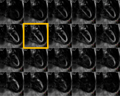
Figure.1 MoSe-CINE
images allows direct visualization of motion-independent cardiac phase timing. It shows depicted signal decrease due to cardiac
motion and it pointed out when is the best timing to trigger for both systolic
and diastolic timings.
-
Model-based motion correction outperforms a model-free method in quantitative renal MRI
Fotios Tagkalakis1, Kanishka Sharma2, Irvin Teh1, Bashair al-Hummiany1, David Shelley1, Margaret Saysell3, Julie Bailey3, Kelly Wroe3, Cherry Coupland3, Michael Mansfield3, and Steven Sourbron2
1University of Leeds, Leeds, United Kingdom, 2University of Sheffield, Sheffield, United Kingdom, 3Leeds Teaching Hospitals NHS Trust, St James's Hospital, United Kingdom
Model-driven registration is faster
and more effective than model-free registration for motion correction in multiparametric,
quantitative MRI of the kidney.
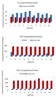
Figure 3. Comparison of computational times in minutes per
patient (1-10) for GFMR (red) and MDR (blue) methods on T1 (top), DTI (middle) and
DCE (bottom).
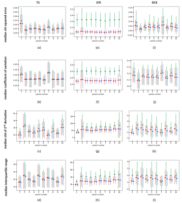
Figure 2. Distribution of pixel-based median metrics (one
per row) for all 3 contrast mechanisms (one per column) and for each individual
subject (horizontal axis). Plots show median +/- standard deviation for
uncorrected data (green), GFMR (red) and MDR (blue).
-
Motion-robust T2-weighted TSE imaging in the prostate by performing non-rigid registration between averages
Katja Bogner1, Elisabeth Weiland2, Thomas Benkert2, and Karl Engelhard1
1Institute of Radiology, Martha-Maria Hospital, Nuremberg, Germany, 2MR Application Predevelopment, Siemens Healthcare GmbH, Erlangen, Germany
T2-weighted
imaging has high relevance in prostate MRI but is prone to motion-induced
blurring caused by slight displacements between averages. Non-rigid
registration before averaging results in reduced motion artifacts and improves
image quality and diagnostic validity.
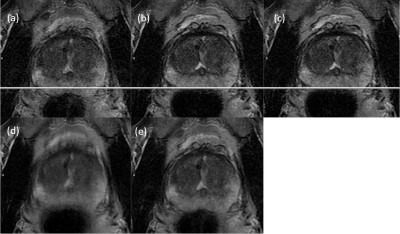
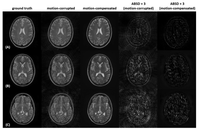
Figure 1: Typical
motion in T2-weighted imaging with averaging
(a-c) single average with degraded image quality and displacement shift
(d) combination of all averages without MOCO
(e) combination of all averages with MOCO and improved image quality
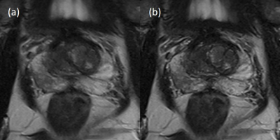
Figure 2: Improved
image quality of MOCO
(a) conventional reconstruction
(Likert-score 3)
(b) MOCO (Likert-score
1)
-
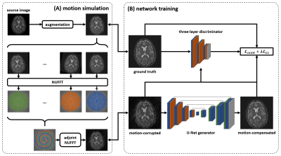
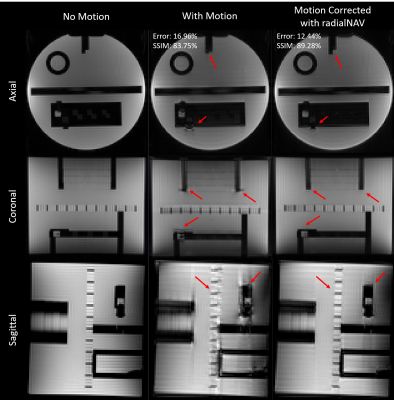
Motion Correction of Abdominal Diffusion-Weighted MRI Using Internal Motion Vectors
Michael Bush1, Thomas Vahle2, Uday Krishnamurthy1, Thomas Benkert2, Xiaodong Zhong1, Bradley Bolster1, Paul Kennedy3, Octavia Bane3, Bachir Taouli3, and Vibhas Deshpande1
1Siemens Medical Solutions USA, Inc., Malvern, PA, United States, 2Siemens Healthcare GmbH, Erlangen, Germany, 3The Department of Radiology and Biomedical Engineering and Imaging Institute, Icahn School of Medicine at Mt. Sinai, New York, NY, United States
Motion vectors derived from non-rigid registration of low
b-value diffusion volumes can be used to correct for motion in higher b-values.
Initial results suggest the proposed method can produce images similar in
quality to respiratory gating, while maintaining reduced acquisition times.
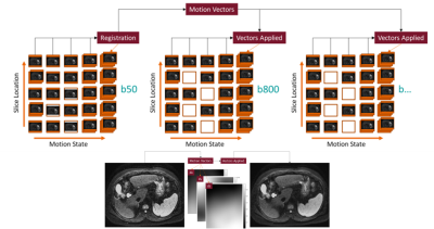
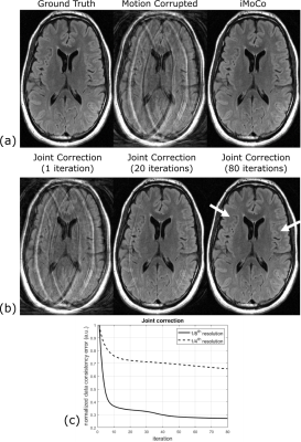
Figure 1. Flow diagram of the iMoCo process.
Redundant sampling of the b50 volumes results in well-filled motion states,
allowing for accurate non-rigid registration. Motion vectors produced by the
non-rigid registration are then applied to the remaining b-value volumes, which
do not require redundant sampling.
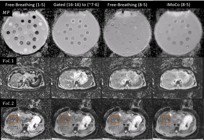
Figure 3. Motion Phantom (MP) and Healthy Volunteer ADC
Maps (Voxel size 1.5x1.5x5.0 mm3, PAT 2, Matrix Size 128x104x35, FOV
380 mm, TR 6.1 s, TE 56 ms, b50-16 avgs, b800-16 avgs, BW 2300 Hz/Px). Motion
Phantom diffusion values are most comparable between the gold-standard Gated
and iMoCo maps.
-
High Resolution PET/MR Imaging Using Anatomical Priors & Motion Correction
Mehdi Khalighi1, Timothy Deller2, Floris Jansen2, Mackenzie Carlson3, Tyler Toueg4, Steven Tai Lai1, Dawn Holley1, Kim Halbert1, Elizabeth Mormino4, Jong Yoon1, Greg Zaharchuk1, and Michael Zeineh1
1Radiology, Stanford University, Stanford, CA, United States, 2Engineering Dept., GE Healthcare, Waukesha, WI, United States, 3Bioengineering, Stanford University, Stanford, CA, United States, 4Neurology, Stanford University, Stanford, CA, United States
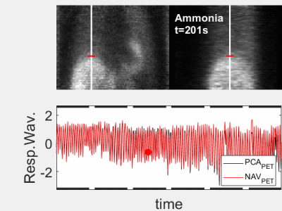
PET image reconstruction with anatomical priors is used within the framework of rigid motion correction for PET/MR brain images to address the co-registration problem between anatomical priors and PET coincident events. The results show improved image resolution in addition to higher SNR.
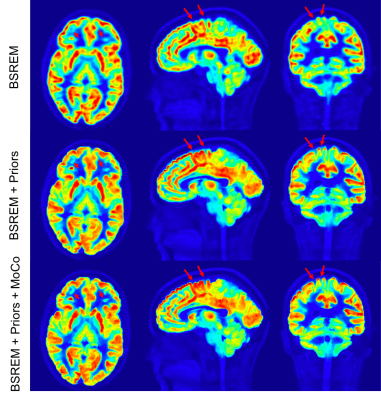
Figure 2: Comparison of 11C-UCBJ PET images reconstructed with conventional BSREM (top row), MR guided BSREM using the anatomical priors without motion correction (middle row) and MR guided BSREM with motion correction (bottom row). MR guided BSREM shows better SNR and higher image resolution compared to the BSREM method; however, as shown by red arrows, incorporating motion correction into MR guided BSREM (bottom row), results in a sharper image with crisper edges.
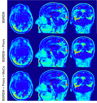
Figure 4: Comparison of 18F-PI2620 PET images reconstructed with conventional BSREM (top row), MR guided BSREM using the anatomical priors without motion correction (middle row) and MR guided BSREM with motion correction (bottom row). MR guided BSREM shows better SNR and higher image resolution compared to the BSREM method and as shown by red arrows (e.g., pituitary gland and right occipital & parietal cortex), incorporating motion correction into MR guided BSREM (bottom row), results in a sharper image; however, because of the lower counts on this exam, less improvement is observed.
-
Ultra-wide-band radar for respiratory motion correction of T1 mapping in the liver
Tom Neumann1, Juliane Ludwig1, Kirsten M. Kerkering1, Frank Seifert1, and Christoph Kolbitsch1
1Physikalisch-Technische Bundesanstalt (PTB), Braunschweig and Berlin, Germany
Respiratory motion correction of T1 mapping in the liver based on a calibrated ultra-wide-band radar signal. A linear model was used to predict respiratory motion during data aqcuisition and improve the image quality in T1 maps.
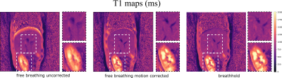
Figure 4: The motion corrected
T1 maps show an increase in image quality. Respiratory blurring especially at the dome of the liver and around blood vessels could be reduced yielding similar image quality than the breathholdscan. Although the motion model was built for the liver, also the visualization of the kidneys is improved. It should be noted, that the breathhold data cannot be directly
compared to motion corrected images, because they were acquired in two separate scans.
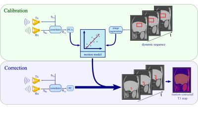
Figure 1: Calibration: The M-sequence STx gets transmitted
by a sending antenna Tx and correlated with the received response SRx to
create an impulse response Rxy. The principal components of Rxy
get linearly fitted to the registered changes in a selected region of
interest in the dynamic scan. Correction:
Based on the motion model, radar signals obtained simultaneously to the T1
mapping sequence are used to predict respiratory motion shifts which can then
be utilized during image reconstruction to correct for motion artefacts.
-
Detecting Respiratory Motion Using Accelerometer Sensors: Preliminary Insight
Eddy Solomon1,2, Syed Saad Siddiq1,2, Daniel K Sodickson1,2, Hersh Chandarana1,2, and Leeor Alon1,2
1Radiology, New York University School of Medicine, New York, NY, United States, 2New York University Grossman School of Medicine, New York, NY, United States
MRI-compatible accelerometers for tracking respiratory motion showed
reliable results in tracking motion when compared to conventional k-space
self-navigation. Its small dimensions and flexible high sampling rate offer
great potential for tracking of breathing signals.
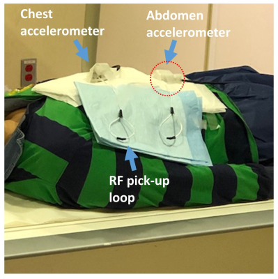
Figure 2. Experiment
setup with the accelerometer placed on top of the abdomen.
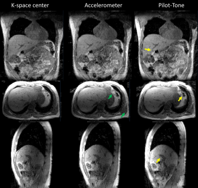
Figure 5. 3D view of data binned by k-space center (left
column), accelerometer (middle column) and Pilot-Tone RF transmitter (right
column). Data binned by the three methods were found to be in good agreement. Additionally,
data binned using the accelerometer signal showed fine tissue boundaries (green
arrow) and data binned using Pilot-Tone showed finer liver anatomical details
(yellow arrows).
-
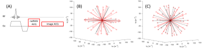
Detection of Head Motion using Navigators and a Linear Perturbation Model
Thomas Ulrich1 and Klaas Paul Pruessmann1
1Institute for Biomedical Engineering, ETH Zurich and University of Zurich, Zurich, Switzerland
Our algorithm achieved high accuracy and precision during the phantom experiment. RMS error was about 25 micrometers for all translation directions, and 0.04 degrees around all rotation axes. It was also able to estimate motion of our volunteer during the in-vivo experiments.
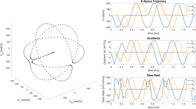
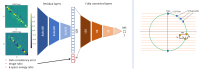
Orbital navigator k-space trajectory. Left: Parametric plot of the trajectory shape. Right: Plots of the trajectory, gradients, and slew rate over time. The trajectory is made up of three orthogonal circles, with smooth transitions in between them. At a radius of 200 rad/m, the navigator gradients can be executed in about 1.65 milliseconds.
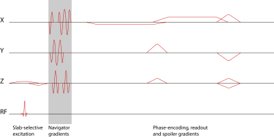
Sequence diagram of a 3D T2*-weighted FFE sequence with 3D orbital navigator gradients inserted after the excitation and before the phase-encoding gradients.
-
Effects of geometric distortions on navigator accuracy for motion corrected brain imaging at 7T
Mads Andersen1 and Vincent Oltman Boer2
1Philips Healthcare, Copenhagen, Denmark, 2Danish Research Centre for Magnetic Resonance, Centre for Functional and Diagnostic Imaging and Research, Copenhagen University Hospital Hvidovre, Hvidovre, Denmark
Brain imaging at 7T can benefit from motion
correction. EPI can reduce navigator durations. We investigated the accuracy for volume navigators of different resolutions and EPI readout durations. The
realignment error grows with the size of motion, voxel size, and EPI readout
duration.
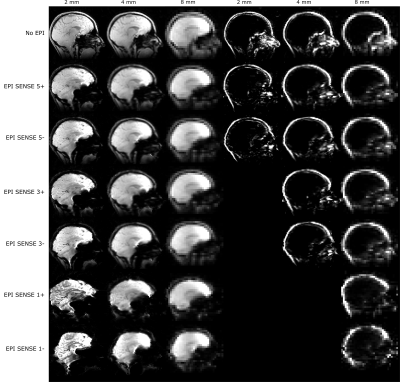
Figure 1: Examples of the simulated navigators. Water navigators
left, fat navigators to the right. Fat navigators were not simulated for echo
times of 10 ms and larger, because of the short T2* of fat.
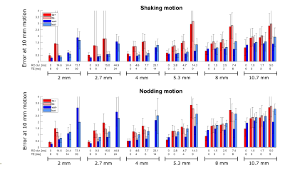
Figure 5: The
fit value (see figure 4) at 10 mm motion score of the golden standard, for all
navigators simulated. For each resolution the readout durations (RO dur.) and echo times correspond
to (from left to right): No EPI, EPI SENSE 5, EPI SENSE 3, EPI SENSE 1.