-
Rapid high power transmit-receive switching using a timed cascade of PIN diodes
Christoph Michael Schildknecht1, Markus Weiger1, Romain Froidevaux1, and Klaas Paul Pruessmann1
1Institute for Biomedical Engineering, ETH Zurich and University of Zurich, Zürich, Switzerland
For imaging of short-T2
samples often very short excitation pulses are desired, which requires high
peak RF power. In this work, a transmit-receive switch is presented that can
handle 18kW peak RF power and switches its state in less than 1µs.
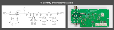
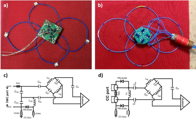
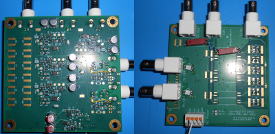
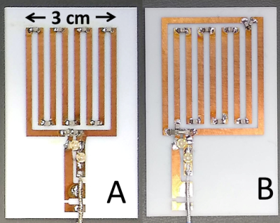
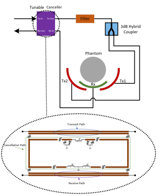
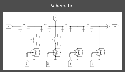
Left: Illustration of
the RF topology of the high-power T/R switch. The antiparallel PIN diode pairs
are driven in a cascaded way. Towards the RX port, PIN diodes with shorter
carrier lifetime are deployed.
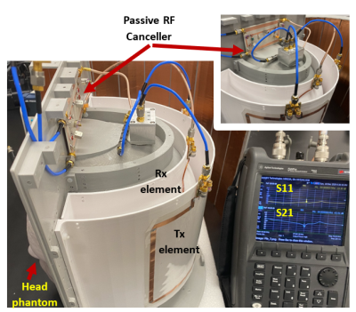
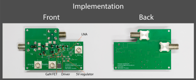
Right: Implementation
of such an RF topology. In addition, auxiliary circuits and low noise amplifier
(LNA) can be seen.
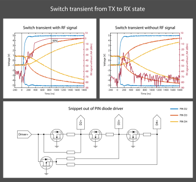
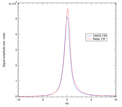
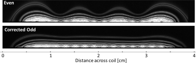
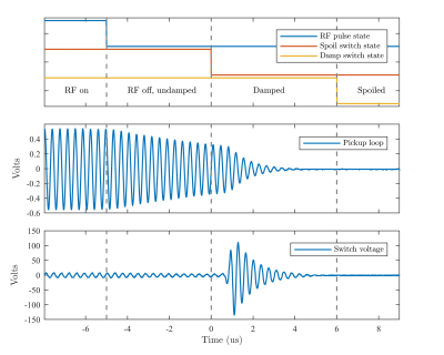
Top row: transient
switch behavior when switching from the TX to the RX state. The reverse bias is
built up in a cascade, which reduces the transient voltage peaks.
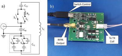
Bottom row: Snippet
out of the passive self-triggered PIN diode driver. As long as a PIN diode is
still in its low impedance state, it has a forward voltage present, despite
bulling a reverse current out of it. When the PIN diode changes to its high
impedance state, current is drawn out of the next stage.
-
Analysis of preamplifier decoupling effect in MRI coil array with electromagnetic field and RF circuit co-simulation
Ming lu1,2, Bei Zhang3, John C. Gore1,2, and Xinqiang Yan1,2
1Vanderbilt University Institute of Imaging Science, Vanderbilt University Medical Center, Nashville, TN, United States, 2Department of Radiology and Radiological Sciences, Vanderbilt University Medical Center, Nashville, TN, United States, 3Advanced Imaging Research Center, University of Texas Southwestern Medical Center, Dallas, TX, United States
We proposed an RF
circuit and EM field co-simulation method that can evaluate the preamplifier
decoupling in terms of the resonate response difference, B1, and SNR. This
method has been used in analyzing the preamplifier decoupling performance of
different types of coil.
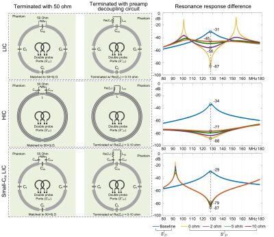
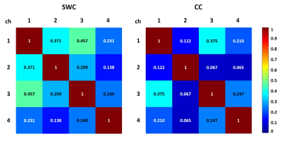
Figure 3. Circuit-level
simulation results of the preamp decoupling abilities in different types of
coil. This ability was evaluated by the resonate response difference between
the termination of 50Ω and the termination of the preamp. The real part of the
preamp (Re[Zin]) was set with different values from 0Ω to 10Ω. In practice,
Re[Zin]< 5 Ω is recognized as an acceptable low-input impedance. For LIC,
Cm=59.9 pF and Ct= 33.1pF. For HIC, Lm= 483.8 nH and Cms= 7.1 pF. For small-Cm
LIC coil, Cm = 5.5 pF, Ct = 1000 pF and Cms = 7.1 pF.
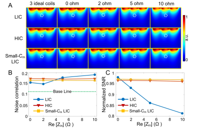
Figure 5. SNR
and noise correlation simulation results. A: Calculated SNR maps in the central
transverse slice. B: Average noise correlation of neighbor coils (i.e.,
left-middle and right-middle coils). C: Calculated SNR values in an 8-cm-deep
region that is directly under the middle coil.
-
Should coaxial coils be operated at their self-resonance? A simulation study
Sigrun Roat1, Andre Kuehne2, Lena Nohava1,3, and Elmar Laistler1
1High Field MR Center, Center for Medical Physics and Biomedical Engineering, Medical University of Vienna, Vienna, Austria, 2MRI.TOOLS GmbH, Berlin, Germany, 3CEA, CNRS, Inserm, BioMaps (Laboratoire d'Imagerie Biomédicale Multimodale Paris Saclay), Université Paris-Saclay, Orsay, France
Our simulations show
that it is advantageous to operate the coil close to their self-resonance
frequency. This might be achieved by changing the size of the coil or introducing
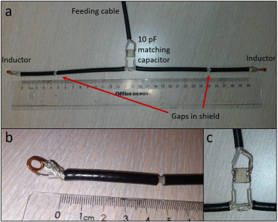
additional gaps in order to shift the self-resonance.
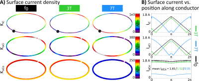
Fig. 1A) Surface
current density plots for the coil setup A1 (100 mm diameter) evaluated at
frequencies for 3T (top) and 7T (middle) MR as well as at its f0
(109 MHz, bottom) on the three substructures iC, oCi and oCo. B) shows the
corresponding surface current plots for all three frequencies (3T, 7T and f0
in green, blue and black, respectively) on the aforementioned substructures.
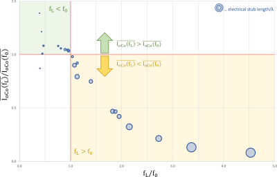
Fig. 2 Simulation
results for all setups. Ratio of the mean surface current at the operating
(Larmor) frequency over at self resonance plotted against the deviation from
the self-resonance fL/f0. The size of each data point is
proportional to the electrical stub length over the wavelength in the cable.
-
Conformal design of radio-frequency head coil for ultra-high field MRI
Tiago Martins1, Tales Santini1, Jacob Berardinelli1, Anthony DeFranco1, and Tamer S Ibrahim1
1University of Pittsburgh, Pittsburgh, PA, United States
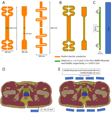
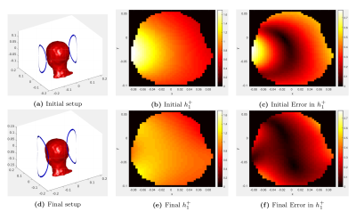
We presented examples of the conformal Tic Tac Toe model for
different head coil design configurations for ultra-high field MRI. The
conformal model yields improved coil performance metrics and allows the
flexibility in design.
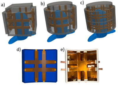
Figure 1: Representation of simulation design for a) the current 16 channels
Tic Tac Toe (TTT) coil; b) the conformal 16 channels TTT coil; c) the
new conformal 32 channels TTT coil with 2 channels per panel. A single
panel of the 32 channels conformal design is represented in d) and the
photo of the actual built panel is represented in e).
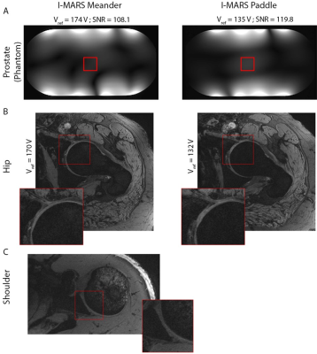
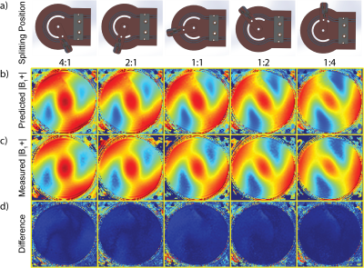
Figure 4: Comparison between the magnitude of experimental B1+ maps of a
conformal (a) and a planar (b) 4.25in Tic Tac Toe panels, acquired using
the same spherical phantom at approximately the same distance between
the panel and the phantom. The B1+ maps shown are the center slices for
each orientation (axial, sagittal and coronal). Intensities are
normalized to the same scale.
-
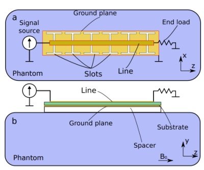
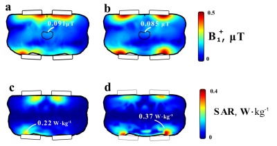
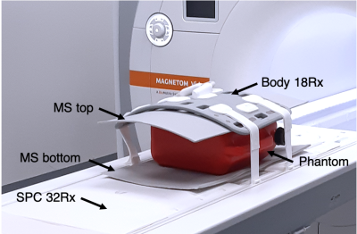
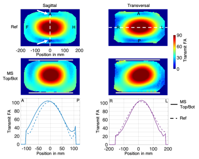
Safety and imaging performance of 2-channel RF shimming for fetal MRI at 3T
Filiz Yetisir1, Esra Abaci Turk1,2, P. Ellen Grant1,2,3, Elfar Adalsteinsson4,5, and Lawrence L. Wald3,5,6
1Fetal-Neonatal Neuroimaging and Developmental Science Center, Boston Children's Hospital, Boston, MA, United States, 2Department of Pediatrics, Harvard Medical School, Boston, MA, United States, 3Department of Radiology, Harvard Medical School, Boston, MA, United States, 4Department of Electrical Engineering and Computer Science, Massachusetts Institute of Technology, Cambridge, MA, United States, 5Harvard-MIT Division of Health Science and Technology, Massachusetts Institute of Technology, Cambridge, MA, United States, 6Athinoula A. Martinos Center for Biomedical Imaging, Massachusetts General Hospital, Charlestown, MA, United States
Two-channel
RF shimming at 3T can be used to improve transmit field amplitude and uniformity
for fetal MRI without increasing maternal or fetal SAR in some pregnant
subjects. The biggest difference in imaging performance and SAR patterns is observed between left lateral and supine models.
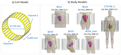
Figure 1: Numerical model of the
2-channel, 32-rung high pass birdcage coil (a) and the numerical pregnant body
models (b) used in this study. Only the skin, uterus and fetus are shown in the
body models for simplicity. GA: gestational age, w: weeks, BMI: body mass
index.
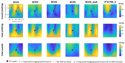
Figure 3: Overall (maternal and
fetal) peak local SAR, fetal peak local SAR and fetal average SAR for different RF shim
settings where relative amplitude and phase of the two channels is varied from 0 to 2 (vertical axis) and from -90° to 270° (horizontal axis) respectively. All shim settings are normalized to maternal
whole-body average SAR of 2 W/kg. CP mode: circularly polarized birdcage mode,
improved imaging performance: both average B1+ and B1+ variation
is improved compared to CP mode, no SAR increase: maternal or fetal SAR does
not increase compared to CP mode.
-
Stabilization of bias field on 3D MPRAGE at 7T with dielectric pads and 3D-based B1+ scaling
Giske Opheim1, Vincent O. Boer2, Esben Thade Petersen2,3, Martin Prener1, Olaf B. Paulson1,4, and Jan Ole Pedersen5
1Neurobiology Research Unit, Dept. of Neurology, Copenhagen University Hospital Rigshospitalet, Copenhagen, Denmark, 2Danish Research Centre for Magnetic Resonance, Centre for Functional and Diagnostic Imaging and Research, Hvidovre, Denmark, 3Section for Magnetic Resonance, DTU Health Tech, Technical University of Denmark, Kgs. Lyngby, Denmark, 4Faculty of Health and Medical Sciences, University of Copenhagen, Copenhagen, Denmark, 5Philips Healhtcare, Copenhagen, Denmark
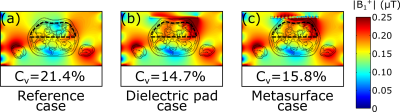
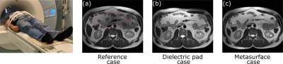
The coefficient of
variation (CV) of bias fields varied significantly between three different B1+
control approaches. A combination of large pads and 3D-based RF gain optimization
yielded the smallest variations of CV, indicating increased stability.
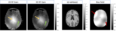
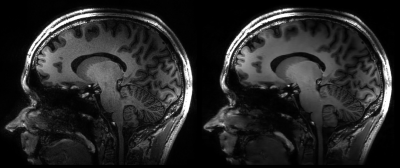
Figure 1:
Two images to the left: Examples of B1+ maps after 2D and 3D RF gain optimization from the same subject. The 2D gain optimization
for this subject caused B1+ of 160% in the center of the brain. The 3D
optimization caused B1+ of 140% (yellow arrows).
The green arrows indicate lateral area typically presenting B1-induced
inhomogeneity whose severity vary particularly with head size and placement of
dielectric pads.
Two right images: Example of a bias field corrected 3D
MPRAGE image and the computed bias field. The red arrows demonstrates
40% MPRAGE magnitude variations.
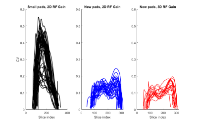
Figure 2:
Plots showing variability of CV across the
slices in the individual brainmasks for group 1 (black, n=48), group 2 (blue,
n=29) and group 3 (red, n=18). The slice-indexing is feet-head, i.e. high
numbers corresponds to the top of the head.
-
The impact of B1+ on the optimisation of high-resolution ASL acquisitions at 7T
Sriranga Kashyap1, Roy A. M. Haast2, Thomas F. Kirk3, An T. Vu4,5, Denizhan Kurban1, Ron Hellenbrand1, Christopher J. Wiggins6, Alard Roebroeck1, Ali R. Khan2, David A. Feinberg1,7,8, Benedikt A. Poser1, and Dimo Ivanov1
1Department of Cognitive Neuroscience, Maastricht University, Maastricht, Netherlands, 2Centre for Functional and Metabolic Mapping, Western University, London, ON, Canada, 3University of Oxford, Oxford, United Kingdom, 4University of California, San Francisco, CA, United States, 5San Francisco Veteran Affairs Health Care System, San Francisco, CA, United States, 6Scannexus B.V., Maastricht, Netherlands, 7Advanced MRI Technologies, Sebastopol, CA, United States, 8Helen Wills Neuroscience Institute, University of California, Berkeley, CA, United States
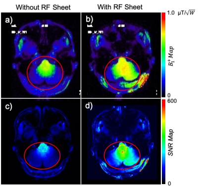
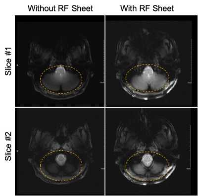
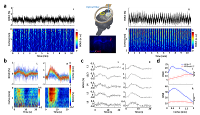
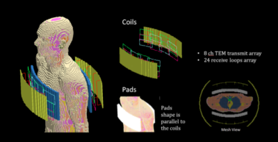
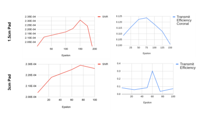
In this 7T study, we show that B1+ distribution can be improved by optimising the placement of dielectric pads. We demonstrate that B1+ has a direct impact on perfusion measurements using ASL at 7T and therefore, on potential clinical utility.
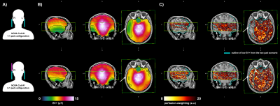
Figure 3: The data acquired on subj-02 on the same scanner using NOVA Coil #1 with two different dielectric pad configurations. (A) Schematic of dielectric pads placement (pink is the additional pad used), (B) B1+ maps (C) perfusion-weighted images. Overlaid rectangular outline indicates the slab coverage for perfusion imaging and cyan outline is the low B1+ from the 1-1 configuration. Note the impact of the 2-1 pad configuration, best illustrated in the axial slices.
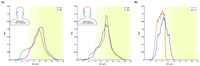
Figure 4: (A) B1 histograms in left and right hemispheres of subj-02 for 1-1 and 2-1 dielectric pad configuration (inset schematic) (B) Histogram showing the improvement in B1+ in the 2-1 configuration (region-of-interest is the low B1+ outline in Fig 3B top row). Yellow background and dotted line indicate 95% efficiency threshold for the tr-FOCI inversion pulse.
-
Is it feasible to Make More Effective Use of Finite RF Power Resources in pTx Systems Using a Coupling Matrix?
Stephen E. Ogier1, Shaihan Malik1, and Joseph Hajnal1,2
1Biomedical Engineering Department, School of Biomedical Engineering and Imaging Sciences, King's College London, London, United Kingdom, 2Centre for the Developing Brain, School of Biomedical Engineering and Imaging Sciences, King's College London, London, United Kingdom
RF networks have been investigated that allow the sharing of
transmit power between channels. These have the potential to increase the
maximum transmit field a given coil and set of RF power amplifiers can produce.
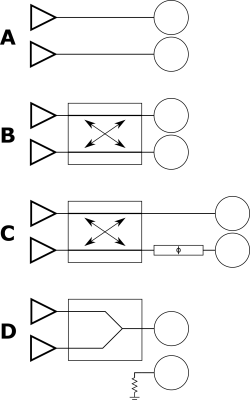
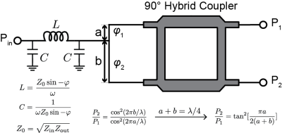
Four proposed structures for exciting two coil elements with
two RFPAs. A Conventional pTx excitation with one dedicated amplifier per
coil. B Power sharing with a 90° hybrid coupler. C Power sharing with
a 90°
hybrid coupler and phase shifter. D Power combination with a Wilkinson power
combiner.
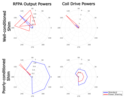
Top row is a shim well-suited to power sharing and bottom
row is a shim poorly-suited. Left column shows RFPA output power for the
standard system and system with the power sharing network. The right column
shows coil drive power levels for the standard system and power sharing
network.
-
Design of transmit array coils by minimizing the modal reflected power values and increasing B1+ efficiency
Ehsan Kazemivalipour1,2, Giorgio Bonmassar3, Laleh Golestanirad4,5, and Ergin Atalar1,2
1Electrical and Electronics Engineering Department, Bilkent University, Ankara, Turkey, 2National Magnetic Resonance Research Center (UMRAM), Bilkent University, Ankara, Turkey, 3AA. Martinos Center, Massachusetts General Hospital (MGH), Harvard Medical School, Boston, MA, United States, 4Department of Radiology, Feinberg School of Medicine, Northwestern University, Chicago, IL, United States, 5Department of Biomedical Engineering, McCormick School of Engineering, Northwestern University, Evanston, IL, United States
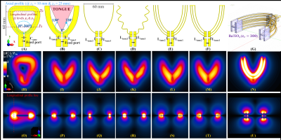
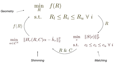
Performing the co-simulation of TxArray coils and extracting the field profiles of the coil's lumped ports/elements provide the opportunity to involve the field-dependent parameters in the minimization procedure of finding the coil's capacitors.
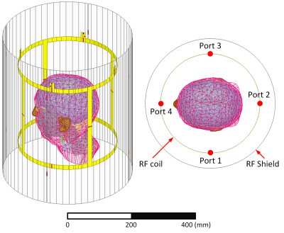
Figure 1 – EM simulation model of a shielded 3T 4-channel TxArray coil loaded with a detailed human head model12. The shield is slit into four segments evenly distributed along the axial direction, where the adjacent slits are connected via two 3 nF capacitors at positions facing the coil's end-rings.
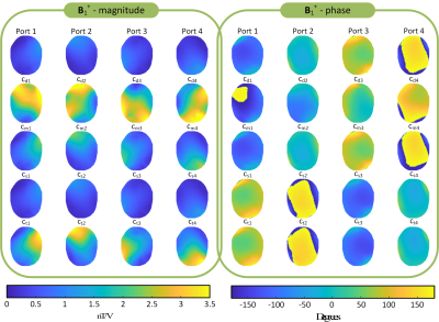
Figure 4 - Magnitude and phase profiles of the B1+ field for all lumped ports/elements in the central axial plane. For each B1+ profile, the corresponding port was fed by a 1 volt, and other ports were terminated.
-
Brain perfusion imaging using pseudo-continuous arterial spin labelling MRI: impact of RF coil shimming of the labelling region
Sofia Guterres1, Ana Rodrigues Fouto1, Nuno André Silva2, Pedro Vilela3, and Patrícia Figueiredo1
1Institute for Systems and Robotics - Lisboa and Department of Bioengineering, Instituto Superior Técnico, Universidade de Lisboa, Lisboa, Portugal, 2Hospital da Luz Learning Health, Lisboa, Portugal, 3Hospital da Luz, Lisboa, Portugal
Simulations show that pCASL labelling efficiency depends on magnetic field inhomogeneity. In vivo data show no evidence of improved labelling efficiency or perfusion signal by using RF coil shimming of the labelling region.
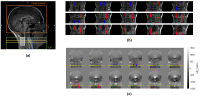
Fig. 1 - (a) Sagittal T1-weighted image indicating the pCASL imaging region (orange), TOF coverage (green), labelling plane (yellow), position of coronal slices for ROI definition as depicted in (b) (blue), and control region for field homogeneity (white); (b) TOF coronal slices showing the ICA (red) and VA (blue) ROIs; and (c) corresponding B0 fieldmap space (where the labelling plane is depicted in yellow), from which the ∆B0 values are extracted for the artery ROIs.
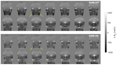
Fig. 3 - B0 fieldmap for an illustrative subject, with RF coil shiming “off” (top) and “on” (bottom). The reduction in field inhomogeneity between the shim “off” and “on” conditions is evident in the posterior neck region, as indicated by the arrows.
-
The Impact of Quasi-Transverse Electric Modes Excited by Dipole Antennas on Transmit Field in In Vivo Ultrahigh Field MRI
Daniel Wenz1,2 and Rolf Gruetter1,3
1CIBM Center for Biomedical Imaging, Lausanne, Switzerland, 2Animal Imaging and Technology, Ecole Polytechnique Federale de Lausanne (EPFL), Lausanne, Switzerland, 3Laboratory of Functional and Metabolic Imaging (LIFMET), Ecole Polytechnique Federale de Lausanne (EPFL), Lausanne, Switzerland
We conclude that the approach presented in this study
has potential to provide new insights into dielectrically-shortened dipole
antenna design and may be particularly relevant given the growing number of
such antenna designs for UHF-MRI.
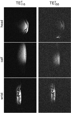
Fig. 5.
In vivo MRI experiments (3D-GRE:
TR/TE = 6.5/2.82ms, FOV = 256x240 mm2, slice thickness = 1.0 mm, FA = 4º,
reference transmit voltage = 100 V) in one human male subject using two blocks:
thinner (d/b = 0.25) and thicker one (d/b = 0.75). Three different regions of
interest (head, calf, wrist) were investigated. The quality of all of the
images was significantly compromised for the larger block (very noisy). The
overall quality of the images depended on the level of curvature of the
anatomical structure. The acquisition parameters of the RF pulse sequence were
used to scan each body part.
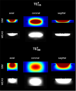
Fig. 4.
Visualization of dielectric modes: the comparison between the electromagnetic
field simulations and MR measurements for two elements: thinner one (d = 0.25b) and thicker one (d =
0.75b). GRE imaging was used
(TR/TE=8.6/4.0 ms, FOV=250 x
250 mm2, slice thickness = 7.0
mm, FA=15º, reference transmit voltage = 5 V). The simulations are in an
excellent agreement with the measurements and show significantly different
magnetic field distribution between the blocks. The mode that propagates within
the thinner block was interpreted as
TE11δz, and within the
thicker one as
TE1δδy.
-
A Novel High Density 32-channel Sleeve Antenna Receiver Array for the Human Head Imaging at 10.5 T
Myung Kyun Woo1, Lance DelaBarre1, Matt Waks1, Russell Lagore1, Jeromy Thotland1, Uk-Su Choi2, Andrea Grant1, Steve Jungst1, Nader Tavaf1, Yigitcan Eryaman1, Kamil Ugurbil1, and Gregor Adriany1
1Center for Magnetic Resonance Research, Minneapolis, MN, United States, 2Center for Information and Neural Networks, Osaka, Japan
Improved peripheral SNR achievable
with the 32-channel sleeve antenna receiver array compared to a 32-channel loop
receiver array of similar dimensions at 10.5 tesla.
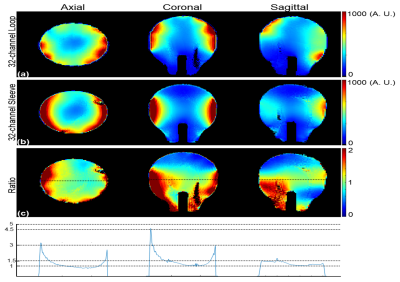
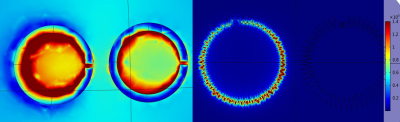
Fig. 4. Intrinsic SNR (iSNR) maps of the
32-channel loop array (a) and 32-channel sleeve antenna (b) arrays with phantom
in the axial, coronal, and sagittal plane. Ratio maps (c) between (b) and (a)
and profiles (d) along the indicated lines.
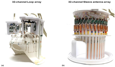
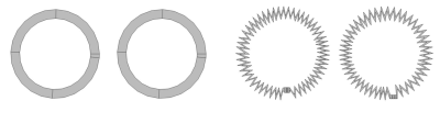
Fig. 1. Photographs of the (a) 32-channel loop
and (b) Sleeve antenna arrays
-
Combining Loops and Dipoles to Increase the Signal-to-Noise Ratio in Human Brain MRI at 7T: How to Shorten a Dipole Antenna?
Thomas Dardano1, Rolf Gruetter1,2, and Daniel Wenz2,3
1Laboratory of Functional and Metabolic Imaging (LIFMET), Ecole Polytechnique Federale de Lausanne (EPFL), Lausanne, Switzerland, 2CIBM Center for Biomedical Imaging, Lausanne, Switzerland, 3Animal Imaging and Technology, Ecole Polytechnique Federale de Lausanne (EPFL), Lausanne, Switzerland
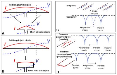
Dielectrically-shortened dipole antenna can be a
promising alternative to its inductively-shortened counterpart in a loop-dipole
combination for human brain MRI at 7T.
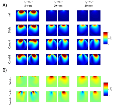
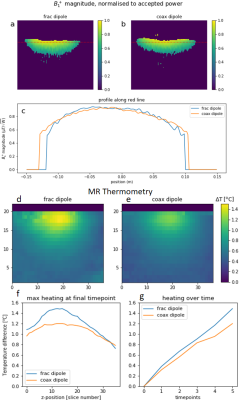
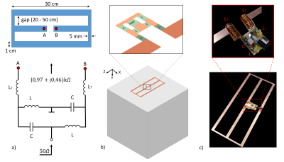
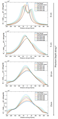
Fig. 3. A) Electromagnetic field simulations: B1+/B1-
field distribution in the spherical phantom as a function of distance (5-mm:
tuned, 20 and 30 mm: detuned). B) Difference maps showing the expected gain in
B1- for the dielectrically-shortened dipole antenna and
its combination with the loop element (especially for the detuned case).
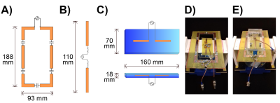
Fig. 1. Simulation view and
photos: A)
Diagram of the loop coil B) Diagram of the inductively-shortened dipole antenna (Ind), C)
Diagram of the dielectrically-shortened dipole antenna (Diel) D) Comb 1 (Loop+Ind) E) Comb
2 (Loop+Diel).
-
Optimization of a massive-element self-decoupled transmit array for 7T head imaging
Ming Lu1,2, John C. Gore1,2, and Xinqiang Yan1,2
1Vanderbilt University Institute of Imaging Science, Nashville, TN, United States, 2Department of Radiology and Radiological Sciences, Vanderbilt University Medical Center, Nashville, TN, United States
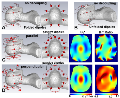
A 48-channel self-decoupled
head coil using the optimized size was simulated with the human model, and it
is found this coil exhibits high inter-element isolation (-15 dB) as well as
the high efficiency.
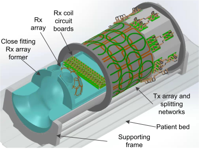
Figure 5: Mechanical design of the 48-channel self-decoupled Tx-only array along with the anatomy-fitting Rx coil. This design could be used for human brain
and spinal cord imaging as well as brain only imaging.
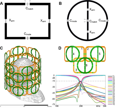
Figure 4: (A) and (B): Diagram of a
single self-decoupled loop (Yan et al, 2018, Nat. Commun.) coil and a single self-decoupled
dipole antenna folded in figure-of-8 shape (Lu et al, 2020, ISMRM). (C)
and (D): Simulation model of the 48-element Tx array and truncated human
model, along with the simulated S-parameter plots of 3 loops and 3 folded
dipoles in two rows. Isolation between any two of 3 loops and 3 dipoles is
better than -15 dB by using self-decoupling technology. Loops in adjacent rows
are overlapped to ensure enough B1 field coverage in the
longitudinal direction (z-direction).
-
High-density 72-channel head array at 7Tesla
Mark Gosselink1, Tijl van der Velden1, Hans Hoogduin1, Martijn Froeling1, and Dennis W. J. Klomp1
1University Medical Center Utrecht, Utrecht, Netherlands
Low noise coupling is observed between an 8-channel
transceiver and a 64-channel receiver array when loaded with the human. When
compared to a 32-channel array, 1/g factor maps substantially improve, paving
way to higher spatiotemporal resolutions.
A 64-channel high-density receiver array as shown is combined with an
8-channel transmit head-coil (not shown).
High resolution (0.8mm isotropic) MPRAGE with SENSE (left) and
Compressed SENSE (right) obtained in 4:35 min.
-
A 30-element transmit array for 7 Tesla brain imaging with array compressed parallel transmission
Charlotte Sappo1,2, Gary R Drake1,3, Xinqiang Yan1,3, and William A Grissom1,2,3,4
1Vanderbilt University Institute of Imaging Science, Nashville, TN, United States, 2Biomedical Engineering, Vanderbilt University, Nashville, TN, United States, 3Radiology, Vanderbilt University, Nashville, TN, United States, 4Electrical and Computer Engineering, Vanderbilt University, Nashville, TN, United States
A 30-channel pTx coil is validated on the bench in phantom measurements for array-compressed parallel transmission. The design presented will enable the mitigation of B1+ field inhomogeneities and control over specific absorption rate in human imaging experiments in the future.
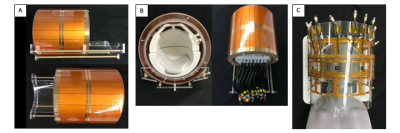
Fig 3. A. Side and top views of the constructed 30-element coil. B. The Nova 32-channel receive coil inserted to show the excellent fit inside the coil. The receive coil sits on an acrylic part so that the pTx coil can slide easily without moving the patient from the helmet. C. The 30-element coil without the shield is shown in detail. All coils are tuned and matching to 298MHz and have a lattice balun at the feedport to reduce cable currents. The head-shaped phantom (The Monster Makers, Cleveland, OH, USA) was filled with a tissue-mimicking solution to tune and match the coil on the bench.
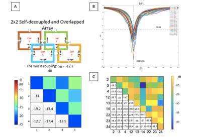
Fig 4. A. The simulation results from a 2x2 self-decoupled and overlapped array in Ansys HFSS (Canonsburg, PA, USA). This decoupling strategy is used throughout the constructed 30-element coil. B. The plot shown is the S11 measurements for all 30 coils at 298MHz. C. A selected set of coupling bench results are shown for a section of the array (coils 2,3,4,12,13,14,22,23,24) for ease of understanding. These decoupling results carry over for the entire coil. All measurements were taken on a Keysight 4-port VNA E5071C and ports that were not being used were terminated using a 50-ohm load.
-
SNR of Flexible Versus Rigid Coil Arrays for Knee MRI
Jeremiah Hess1, Marianne Black2, Feliks Kogan2, and Brian Hargreaves1,2,3
1Department of Bioengineering, Stanford University, Stanford, CA, United States, 2Department of Radiology, Stanford University, Stanford, CA, United States, 3Department of Electrical Engineering, Stanford University, Stanford, CA, United States
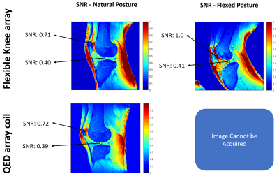
We analyzed the SNR of flex coil-arrays versus a
rigid coil-array in phantom and in vivo to assess which coil had better
SNR. Preliminary results suggest that
flexible coil-arrays show comparable or increased SNR and generally more
uniform SNR over rigid coil-arrays.
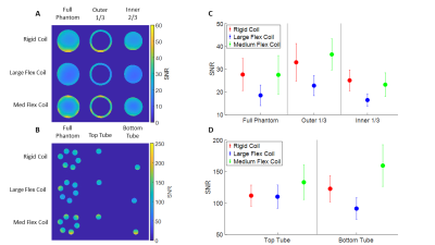
Figure 3: a) SNR Images of cylindrical phantom from
3 different knee coils (Rigid, Medium Flex, Large Flex) for the central slice,
with masked images for the outer 1/3 and inner 2/3 of the phantom b) SNR
Images of 6-tube phantom for the same knee coils at the same slice, with masked
images showing the top and bottom tubes c) Plot of the average SNR with
standard deviation bars for cylindrical phantom images d) Plot of the
average SNR with standard deviation bars for 6-tube phantom images.
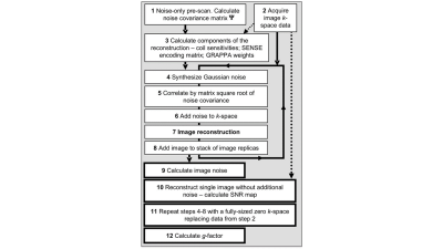
Figure 1: Flow chart of the pseudo-multiple replica method for calculating
SNR shown in Robson et al.3
-
Reduction of coupling and noise by ultrahigh dielectric constant (uHDC) materials for phase array coil at 3T
Navid PourramzanGandji1, Christopher T. Sica2, Gary W. Yang3, Hannes Wiesner4, Soo Han Soon4, Xiao-Hong Zhu4, Michael Lanagan5, Wei Chen4, and Qing X. Yang1
1Neurosurgery, Pennsylvania State University, Hershey, PA, United States, 2Radiology, Pennsylvania State University, Hershey, PA, United States, 3Pennsylvania State University, Hershey, PA, United States, 4Center for Magnetic Resonance Research, Department of Radiology, University of Minnesota, Minneapolis, MN, United States, 5Materials Science and Engineering, Pennsylvania State University, State College, PA, United States
We
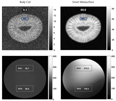
demonstrated experimentally that employing the uHDC materials in a standard clinical
phase array coil could reduce the total noise as well as increase the SNR substantially.
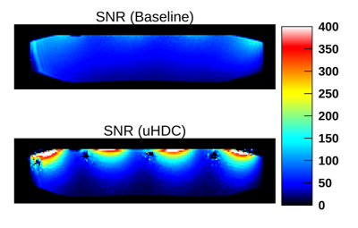
Figure 4) SNR maps (AU) of Baseline and with uHDC blocks. The
SNR is enhanced significantly (up to 4 times near the surface of the phantom).
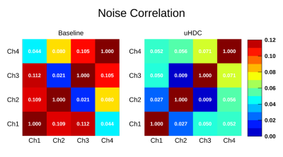
Figure 3) Noise correlation matrix of the Baseline and with
uHDC blocks. This figure shows that the uHDC blocks reduce considerably the
noise correlation between adjacent loops as well as non-adjacent loops.
-
A novel characterization method of HTS non-linear electrical properties using MRI
Aimé Labbé1, Isabelle Saniour1, Rose-Marie Dubuisson1, Jean-Christophe Ginefri1, Luc Darrasse1, and Marie Poirier-Quinot1
1Université Paris-Saclay, CEA, CNRS, Inserm, BioMaps, Orsay, France
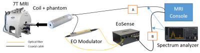
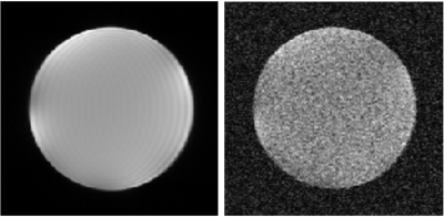
A new characterization
method for the nonlinear electric response of HTS coil is proposed and
validated on a copper surface coil and a HTS surface coil.
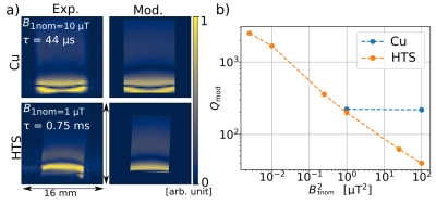
Fig. 1 ― a) Image acquisition (Exp.) and
modelling (Mod.) with a copper (top) and a superconducting (bottom) surface
coils. b) Adjusted quality factor Qmod
as a function of B21,nom evaluated with the model for both the copper
and HTS surface coils.
-
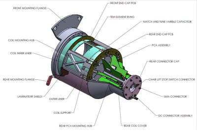
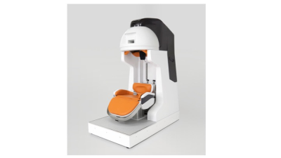
Robot Assisted Dynamic Ankle Joint Imaging with a Wearable 4-Channel High Impedance Coil at 1.5T MRI
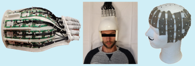
Matthäus Poniatowski1, Ilan Elias2, Mirsad Mahmutovic1, Gurinder Multani1, Sam-Luca J.D. Hansen1, Markus W. May1, Alexander M. König3, Jens H. Figiel3, Andreas H. Mahnken3, and Boris Keil1
1Institute of Medical Physics and Radiation Protection, TH Mittelhessen University of Applied Sciences, Gießen, Germany, 2Motionrad GmbH, Berlin, Germany, 3Department of Diagnostic and Interventional Radiology, Philipps-University Marburg, Marburg, Germany
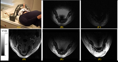
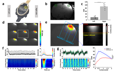
To enable dynamic MRI for joints, an
in-bore motion-assisted device and a wearable coil array was designed,
constructed, and validated. The combination of robotic assisted joint motion, a
tight-fitting coil array, and accelerated imaging enabled dynamic MRI of the
angle.
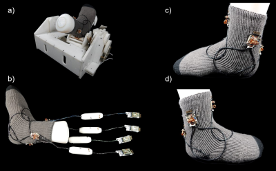
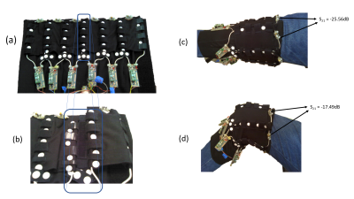
Figure 1: (a) 4-Channel High Impedance Coil placed on the
Robotic Motion Device. (b) Complete view of the 4ch HIC including transmission
lines, cable traps and preamplifiers. (c) Medial and (d) lateral close-up view
without transmission lines, cable traps and preamplifiers.
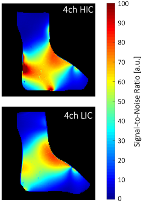
Figure
3: Comparison of SNR maps of
the HIC (top) and the LIC (bottom) using a foot-shaped agar phantom.