-
Ultra-Flexible, High-Resolution, 60-Channel RF Coil for Supine Breast Imaging
Jana Vincent1,2,3, Clyve Konrad Follante1, Ersin Bayram4, Lloyd Estkowski5, Ty Cashen6, Mark Giancola1, Victor Taracila1, Yun-Jeong Stickle1, Lalit Rai1, Venkata Malasani1, Nicole Wake7,8, Vichiry Yan1, Robert Stormont9, Joseph Rispoli2,10, and Fraser Robb1
1GE Healthcare Coils, Aurora, OH, United States, 2Weldon School of Biomedical Engineering, Purdue University, West Lafayette, IN, United States, 3Basic Medical Sciences, Purdue University, West Lafayette, IN, United States, 4Global MR Applications & Workflow, GE Healthcare, Houston, TX, United States, 5Global MR Applications & Workflow, GE Healthcare, Waukesha, WI, United States, 6Global MR Applications and Workflow, GE Healthcare, Madison, WI, United States, 7Albert Einstein College of Medicine, Montefiore Medical Center, Bronx, NY, United States, 8Center for Advanced Imaging Innovation and Research, Department of Radiology, NYU School of Medicine, New York, NY, United States, 9GE Healthcare, Waukesha, WI, United States, 10School of Electrical & Computer Engineering, Purdue University, West Lafayette, IN, United States
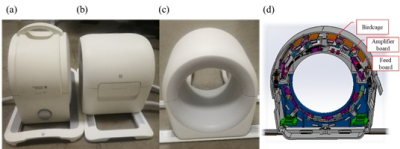
Here we present the first 60-channel, high resolution, lightweight, flexible, supine breast coil. The coil mitigates respiratory and motion artifacts through
high acceleration which is made possible with a high channel count and
commensurate SNR that, in turn, facilitates supine imaging.
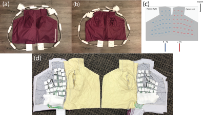
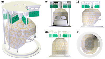
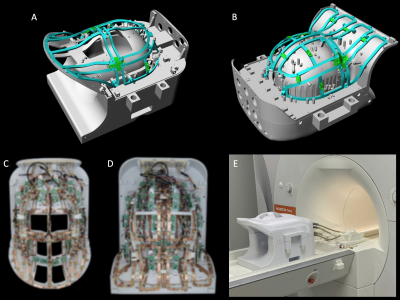
Figure 1. Complete breast/torso coil setup: (a) Front and (b) back mechanical assembly, (c-d) Coil assembly
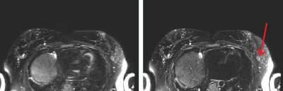
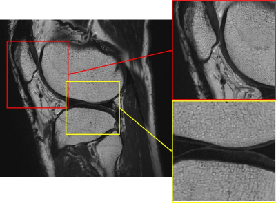
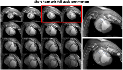
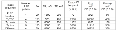
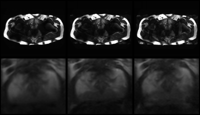
Figure 3. SSFSE,
Left: acceleration factor of 3, Right: acceleration factor of 4. Improved
sharpness is observed with higher acceleration due to reduced T2 blurring resulting
from a shortened echo train. Arrow indicates region of fibroglandular tissue.
-
A Continuously Adjustable 32-Ch Head Coil Array for MRI at 3T
Yunsuo Duan1, Jiacheng Wang2, Feng Liu1, Rachel Marsh1, and Thomas J. Vaughan3
1MR Research, Department of Psychiatry, NYSPI and Columbia University, New York, NY, United States, 2Department of Electrical Engineering, New York University, New York, NY, United States, 3ZMBBI, Columbia University, New York, NY, United States
we presented a novel partially flexible
32-ch coil array to address the difficulty in close fitting for various human
head sizes. The coil array worked
well within size range of 180mm
x 220mm to 220mm x 260mm, which fits for almost all human subjects, while maintaining
desirable comfort.
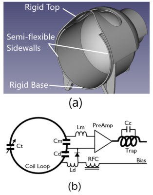
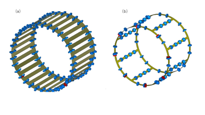
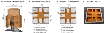
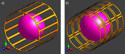
Figure 1. (a) 3D design of the coil former. The upper part (top) is detachable from the lower part for size adjustment. The Top and base are 3D printed using rigid PLA filaments. The sidewalls are 3D-printed using semi-flexible filaments TPU so the sidewalls can be pulled inwards-outwards to shrink/extend the size of the coil. (b) Schematic circuit design of individual coil loop. Ct=15-40pF, Cm=33pF, Cd=24pF, Cc=8.2pF.
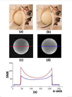
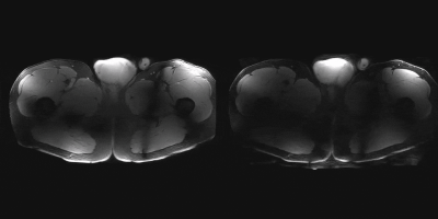
Figure 2. (a) The coil adjusted to 180mmx 220mm and loaded with a sphere phantom in a diameter of 180mm; (b) The coil adjusted to 220mm x 260mm and loaded with the same phantom. (c) A axial-plane image acquired with coil setting (a); (c) A axial-plane image acquired with coil setting (b); (e) SNR distributions along the horizontal center line of image (c) (red) and image (d) (blue).
-
A Quadrature Birdcage/47Rx Coil Array for Acceleration Images on 3 T MRI
Jo Lee1,2, Sen Jia1,2, Liu Liu3, Xiaoliang Zhang4, and Ye Li1,2
1Paul C. Lauterbur Research Center for Biomedical Imaging, Shenzhen Institutes of Advanced Technology, Chinese Academy of Sciences, Shenzhen, China, 2Shenzhen Key Laboratory for MRI, Shenzhen, China, 3United Imaging Healthcare, Shanghai, China, 4Department of Biomedical Engineering, State University of New York, Buffalo, NY, United States
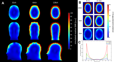
We designed a quadrature-birdcage/ 47Rx head coil array
for accelerated images on 3 T MRI, and has compared to a commercial 32-channel head
coil for quantified analysis. The results show that the 47-channel head coil has
better acceleration ability.
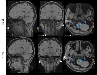
Fig.3. 0.6 mm isotropic modulated
flip angle technique in refocused imaging with extended echo train (MATRIX)
images were acquired using the commercial head coil (32ch; top row) and the quadrature
birdcage/47Rx coil array (47ch; bottom row) at R = 7-fold acceleration. The
acceleration direction was on phase encoding and slice phase encoding. H =
head; P = posterior; R = right; A = anterior.
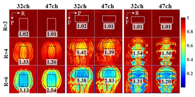
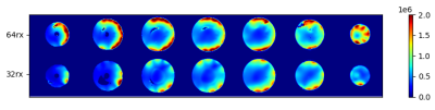
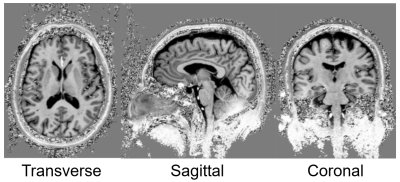
Fig.2. Inverse g-factor maps. To
display coil acceleration ability of each direction, each orientation was
accelerated on different directions. Transverse orientation: Left-to-Right
acceleration direction. Sagittal orientation: Anterior-to-Posterior
acceleration direction. Coronal orientation: Head-to-Feet acceleration
direction. Regions of interest (ROIs) is marked as black dashed line. The mean
g-factor value of each ROI is written beside the related image. L: left, R:
right, A: anterior, P: posterior, H: head, F: feet.
-
A dedicated coil for cerebellar fMRI
Nikos Priovoulos1, Thomas Roos1, Ozlem Ipek2, Ettore Meliado3, Richard Nkrumah2, Dennis Klomp3, and Wietske van der Zwaag1
1Spinoza Center, Amsterdam, Netherlands, 2King’s College London, London, United Kingdom, 3University Medical Center Utrecht, Utrecht, Netherlands
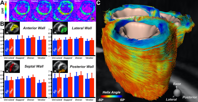
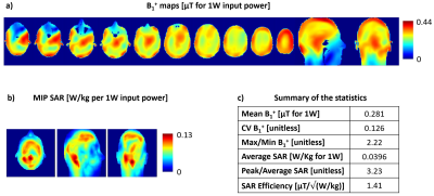
The combination of 32Rx dense surface receives with a dedicated 3Tx transmit results in increased B1+, SNR and BOLD sensitivity in the human cerebellum at 7Tesla.
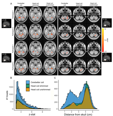
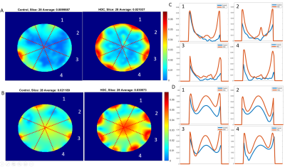
Figure 5: A, (Finger tapping > Rest) BOLD fMRI significant clusters (z>3.1) for 2 sample participants along axial slices at the height of the cerebellum, crossing the hand region in cerebellar lobule V (left) and cerebellar lobule VIII (right). B, Group Z-stat distribution for each coil. C, Barplots of active voxels at group level in relation to the distance from the skull.
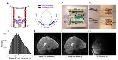
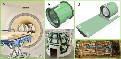
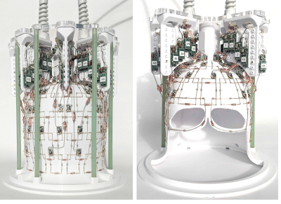
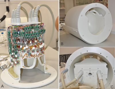
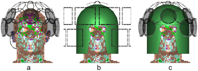
Figure 1: A, view of the cerebellar coil. Red, transmit elements. Blue, receive elements. B, The transmit array (housing partially removed). C, The receive array (open covers). D, Distribution of voxels in the cerebellum with respect to distance from the skull (median distance=2.58cm (dotted line)). E-G, 3D-EPI slices. E, Head coil without B1 shimming. F, Head coil after B1 shimming. G, Cerebellar coil. Note the reduced deeper sensitivity deeper due to the small total surface area.
-
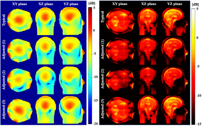
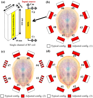
A novel multi-turn histology RF coil design for micro-histological slide imaging
Byung-Pan Song1,2, Sung-Jun Yoon1, Hyeong-Seop Kim1,2, Kyoung-Nam Kim3, and Seung-Kyun Lee1,2,4,5
1Department of Biomedical Engineering, Sungkyunkwan University, Suwon, Korea, Republic of, 2Department of Intelligent Precision Healthcare Convergence, Sungkyunkwan University, Suwon, Korea, Republic of, 3Department of Biomedical Engineering, Gachon University, Incheon, Korea, Republic of, 4Department of Physics, Sungkyunkwan University, Suwon, Korea, Republic of, 5IBS Center for Neuroscience Imaging Research, Suwon, Korea, Republic of
We propose a new multi-turn histology coil for imaging microscopic histological tissue with a higher SNR than previous coil designs.
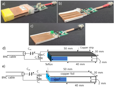
Figure 1. The pictures of the coils and their
schematics. a) U-shaped coil , b) 3-turn solenoid coil, c) 8-turn solenoid
coil. d,e) Schematics of the U-shaped coil and a solenoid coil. e) is citation
from reference[4]. Cm and Ct
enable fine adjustment of the coil impedance matching and resonance frequency
tuning
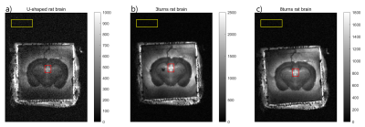
Figure 4. The images of a 40
μm-thick rat brain slice. a) U-shaped coil, b) 3-turn solenoid coil, c) 8-turn
solenoid coil. The signal value was measured in the red square region, and the
noise value was measured in the yellow rectangle. The color scale was adjusted
for each image.
-
How far Should Coil Coverage be Extended to Reach Optimum Simultaneous Multi-Slice Acceleration in Cardiac MRI?
Anpreet Ghotra1, Sam-Luca JD Hansen1, Robin Etzel1, Mirsad Mahmutovic1, Alina Scholz1, Nicolas Kutscha1, Matthäus Poniatowski1, Markus W May1, Choukri Mekkaoui2, and Boris Keil1
1Institute of Medical Physics and Radiation Protection, TH Mittelhessen University of Applied Sciences, Giessen, Germany, 2Harvard Medical School, Massachusetts General Hospital, Department of Radiology, A.A. Martinos Center for Biomedical Imaging, Boston, MA, United States
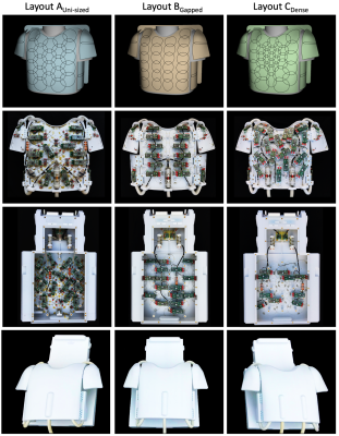
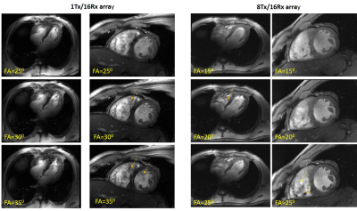
64-channel coil arrays with extended coverage provide more sufficient encoding capacity in SMS-accelerated cardiac imaging than arrays that compactly enclose the cardiac region.
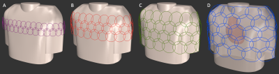
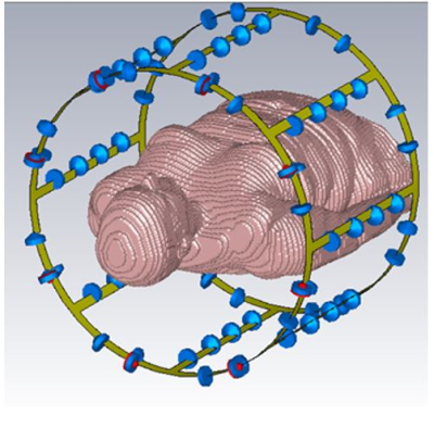
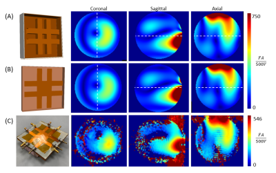
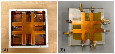
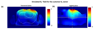
Modelled and simulated circular overlapped coil arrays for highly SMS accelerated cardiac images.
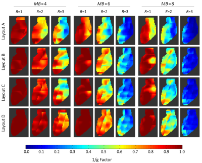
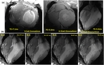
Inverse g-Factor maps of a representative sagittal slice through the heart. g-factors were derived from axial SMS accelerations with multiband factors 4, 6, 8, and additionally combined with in-plane accelerations of R=2 and R=3. The heart region was covered by 60 slices of 2 mm each. 15, 10, and 8 collapsed slices were needed to reconstruct the full heart for MB=4, MB=6, and MB=8, respectively.
-
A novel 16 channel flexible coil for highly accelerated upper-airway MRI
Wahidul Alam1, Rushdi Zahid Rusho1, Scott Reineke2, Madavan Raja2, Stanley Kruger3, Joseph M. Reinhardt1, Junjie Liu4, Douglas Van Daele5, and Sajan Goud Lingala1,2
1Roy J Carver Department of Biomedical Engineering, University of Iowa, iowa city, IA, United States, 2ScanMed LLC, Omaha, NE, United States, 3Department of Radiology, University of Iowa, iowa city, IA, United States, 4Department of Neurology, University of Iowa, iowa city, IA, United States, 5Department of Otolaryngology, University of Iowa, iowa city, IA, United States
We develop a novel custom airway coil to offer significant boost in signal sensitivity in several upper-airway regions. The coil exhibits robust parallel MRI performance up to R=4~5 fold 1-D under-sampling for static imaging, and highly accelerated dynamic imaging (up to R~27 fold).
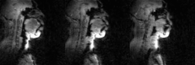
Fig.5 (animation): 2D concurrent multi-slice accelerated dynamic imaging of swallowing an ~10 ml bolus of pineapple juice. Non-Cartesian spiral under-sampling at ~27 fold acceleration level was combined with a sparse SENSE reconstruction scheme. The transport of the bolus is robustly captured in the three sagittal slices with adequate spatial resolution (2.4 mm2), and temporal resolution (17.1 ms).
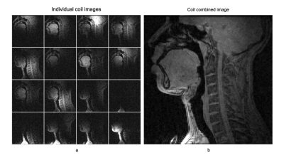
Fig.2: (a) Individual coil images from the 16 channel elements and (b) the R=1 SENSE coil combined image using the proposed airway coil. The coil offers high sensitivity in all upper-airway regions of interest (eg. lips, tongue, hard palate, soft palate, epiglottis, glottis).
-
Signal-to-noise of thermal versus hyperpolarized MRI as a function of field strength and receive coil temperature
Mohammed M. Albannay1, Charles McGrath1, Alexander Jaffray1, and Sebastian Kozerke1
1University and ETH Zurich, Institute for Biomedical Engineering, Zurich, Switzerland
SNR of thermal and hyperpolarized MRI is simulated based on first principles. Hyp. nuclei detection at low field strengths prolong T2* thus reduce readout bandwidth, leading to higher SNR compared to clinical field strengths. SNR gains from coil cooling are studied experimentally at 0.75T
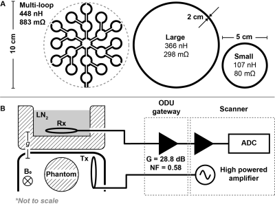
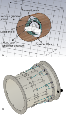
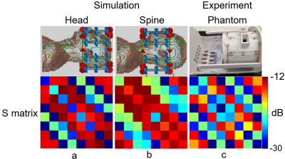
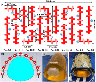
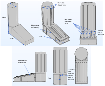
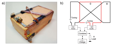
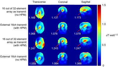
(A) Geometry of the three used receive coils with measured inductance and resistance using a vector network analyser at 32 MHz. The multi-loop coil is printed on 1.6 mm FR4 (1 oz copper), while loop coils are made from $$$(\oslash2 mm)$$$ copper tubing. (B) The coils were hosted in a Styrofoam box and laid parallel to the box surface. Separation $$$g = 2$$$ cm. The phantom was positioned adjacent to a $$$(\oslash5 cm)$$$ transmit coil, under a plastic arc.
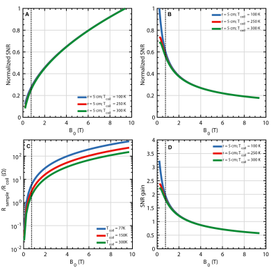
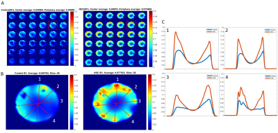
(A) Normalized simulated SNR for thermal and (B) hyperpolarized MRI as a function of field strength and coil temperature, (C) Ratio between equivalent sample and coil resistance. (D) Potential SNR gain relative to 300 K receiver coil at 3T for hyperpolarized MRI. All simulations consider a $$$\oslash$$$ 10 cm coil constructed from $$$\oslash $$$ 2 mm copper wire placed directly on the phantom. Inset dashed line indicating 0.75T.
-
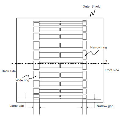
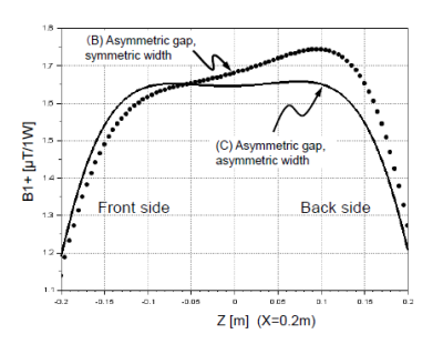
Performance comparison of a 10 cm single-gap vs. double-gap coaxial coil used as a transceiver for 7T MRI
Lena Nohava1,2, Andre Kuehne3, Elmar Laistler1, and Sigrun Roat1
1High Field MR Center, Center for Medical Physics and Biomedical Engineering, Medical University of Vienna, Vienna, Austria, 2BioMaps (Laboratoire d'Imagerie Biomédicale Multimodale Paris Saclay), Université Paris-Saclay, CEA, CNRS, Inserm, Orsay, France, 3MRI.TOOLS GmbH, Berlin, Germany
For 7T MRI, 10 cm double-gap coaxial coil design operated at its self-resonance is advantageous for increased Tx efficiency and slightly lower SAR. Orientation independence of the coil’s B1-field is of importance for free positioning of flexible wearable arrays.
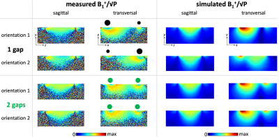
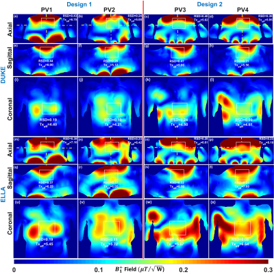
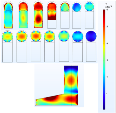
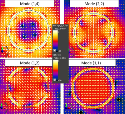
Figure 4: Measured and simulated B1+/√P maps in the central sagittal and transversal slice (FOV=256x256mm2, 0.5x0.5mm2 in-plane resolution, 1.5mm slice thickness, Vref=150V). Different orientations are indicated by black or green dots: their location corresponds to the coil conductor position and their size indicates the oCo current density (inhomogeneous for the 1G, homogeneous for the 2G coil). Thin black lines in transversal measured maps mark the boundaries of regions where the flip angle was higher than the dynamic range of the mapping technique.
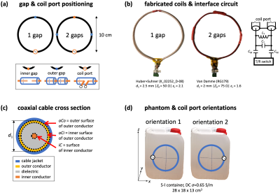
Figure 1: (a) Schematic showing gap positioning, (b) photographs of fabricated coils and interface circuit, (c) coaxial cable cross section, (d) phantom photo and investigated coil orientations.
-
Additive manufacturing of MRI coils by printing and electroplating a conductive polymer
Christoph Michael Schildknecht1 and Klaas Paul Pruessmann1
1Institute for Biomedical Engineering, ETH Zurich and University of Zurich, Zürich, Switzerland
This work reports
additive manufacturing of MRI coils based on 3D printing and electroplating of conductive
polymer. The proposed approach greatly simplifies the fabrication of complex coil and array geometries with a high degree of accuracy and reproducibility.
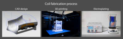
The process has three
major steps. First, the design is made in a CAD software. Then the part is 3D
printed and finally the conductive polymer is electroplated with copper to
increase its conductivity.
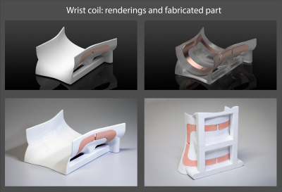
In the top row are
renderings shown for the intended wrist coil. In the bottom row is the actual
3D printed and electroplated coil displayed. Not only does the fabricated coil
look similar as in the renderings, they also closely match the geometrical dimension
as specified in the CAD.
-
Novel antenna array for ultra-high field MR-PET
Chang-Hoon Choi1, Suk-Min Hong1, Jörg Felder1, Lutz Tellmann1, Jürgen Scheins1, Elena Rota Kops1, Christoph Lerche1, and N. Jon Shah1,2,3,4
1INM-4, Forschungszentrum Juelich, Juelich, Germany, 2JARA-BRAIN-Translational Medicine, Aachen, Germany, 3Department of Neurology, RWTH Aachen University, Aachen, Germany, 4INM-11, Forschungszentrum Juelich, Juelich, Germany
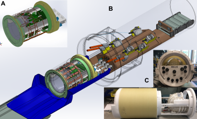
This novel J-pole antenna array is a unique MRI RF probe with exceptionally low gamma attenuation, allowing simultaneous MR-PET and MR-SPECT experiments to be conducted without compromising any aspects of system performance and image quality compared to the stand-alone instrumentation.
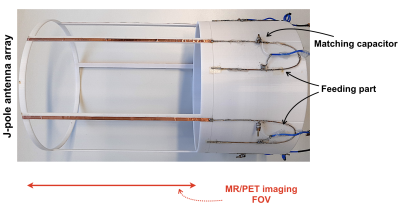
Figure 1. A photograph of the proposed, multi-channel J-pole antenna array showing its essential parts and components.
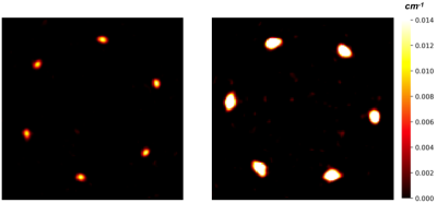
Figure 3. Attenuation maps of the proposed J-pole array (left) and the reference array (right). The centre part of the antennas was measured.
-
Decomposition of the incomplete volume-surface integral equation matrices for MR coil simulations
Ilias Giannakopoulos1, Georgy Dmitrievich Guryev2, Jose Enrique Cruz Serralles2, Ioannis Georgakis1, Luca Daniel2, Jacob White2, and Riccardo Lattanzi1,3,4
1Center for Advanced Imaging Innovation and Research (CAI2R), Department of Radiology, New York University Grossman School of Medicine, New York, NY, United States, 2Department of Electrical & Computer Engineering, Massachusetts Institute of Technology, Cambridge, MA, United States, 3The Bernard and Irene Schwartz Center for Biomedical Imaging (CBI), Department of Radiology, New York University Grossman School of Medicine, New York, NY, United States, 4Vilcek Institute of Graduate Biomedical Sciences, New York University Grossman School of Medicine, New York, NY, United States
The volume-surface integral equation coupling matrix,
that models the interactions between radiofrequency coils and tissue, is reshaped to a set of incomplete tensors and
compressed with the canonical model. Results show 35 times compression for an error
less than 2%, at a 7 T MRI simulation.
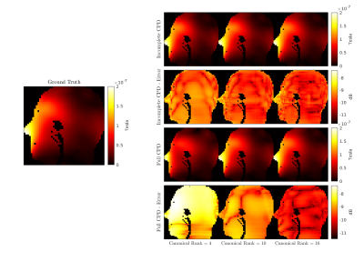
Figure
4: Qualitative comparison
between the simulated
B1+ maps,
for
one representative coil
element of the array and the
middle sagittal slice. The
results for the incomplete and full matrix are displayed for
three canonical ranks (4,10,16), along
with the relative error with respect to the ground truth (left)
in logarithmic scale. Voxels
outside the scatterer are masked for enhanced visualization.
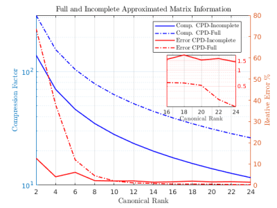
Figure
3: Overall compression factor
(left axis) and relative error (right axis), for the full and
incomplete matrices and various canonical ranks.
-
Flexible Body Coil for Vertical Field MRI using Loop/CRC RF Coil Array
Yosuke Otake1, Takeshi Taniguchi1, Hideta Habara1, Christophor Napier2, Errol Brissett2, Shawn Etheridge2, Masayoshi Dohata1, and Kazuyuki Kato1
1Healthcare Business Unit, Hitachi, Ltd., Tokyo, Japan, 2Hitachi Healthcare Americas, Twinsburg, OH, United States
To improving the SNR and the usability in the vertical field MRI, a flexible body coil using loop/CRC multi-channel array has been developed. SNR of the developed coil 46% better than a conventional coil. This technique will contribute to improve the performance of the vertical field MRI.
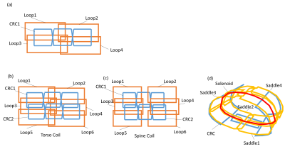
Figure 1. Coil arrangements. (a)Basic configuration of loop/CRC
hybrid multi channel array (LCA) RF coil.(b)Developed torso coil using LCA(8ch). (c)Developed spine coil using LCA(8ch). (d)Conventional body coil for a vertical field MRI(6ch).
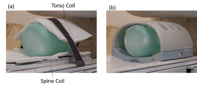
Figure 3. Phantom experiment at 1.2T
vertical field MRI. (a)Developed body coil (LCA torso and spine).
(b)Conventional body coil(SSCA).
-
Design of an over-overlapped wearable 3T pelvic phased array using a capacitor-terminated coaxial coil
Ming Lu1,2, Junzhong Xu1,2, Sandeep S. Arora3, John C. Gore1,2, and Xinqiang Yan1,2
1Vanderbilt University Institute of Imaging Science, Vanderbilt University Medical Center, Nashville, TN, United States, 2Department of Radiology and Radiological Sciences, Vanderbilt University Medical Center, Nashville, TN, United States, 3Department of Radiology and Biomedical Imaging, Yale University School of Medicine, New Haven, CT, United States
Based on our
simulation results, the Capacitor-Terminated Coaxial (CTC) coil is the best
candidate for prostate imaging where a wearable, size-optimized, high-density array
is desired.

Figure 4 A
and B: Simulated receive sensitivity (B1-) maps in the central axial
slice of a cuboid phantom (15x30x15 cm3), with one coil set to 1W input
(active) and the other coil terminated with the preamplifier loading (passive).
The B1- distortion due to non-perfect decoupling can be easily observed in the
residual B1- maps calculated by subtracting the baseline B1- of a single coil.
C and D: Plots of normalized B1- values at the 10-cm-deep region (white dotted
circle in Figures 4A and B).
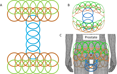
Figure 5 Illustration
of an example of a 29-element high-density over-overlapped coil array focusing
on prostate imaging. A: Planar unfold view. B and C:
Three-dimensional view.
-
An Integrated Radio-Frequency/Wireless (iRFW) Coil Design for Wireless Q-Spoiling During MR Imaging
Jonathan Cuthbertson1,2, Trong-Kha Truong1,2, Jasmine Chen1,2, Fraser Robb3, Allen W. Song1,2, and Dean Darnell1,2
1Medical Physics Graduate Program, Duke University, Durham, NC, United States, 2Brain Imaging Analysis Center, Duke University, Durham, NC, United States, 3GE Healthcare, Aurora, OH, United States
The experiments performed showed
that the integrated RF/wireless coil was able to provide wireless Q-spoiling
during MR image acquisition without significantly impacting SNR or wireless
performance.
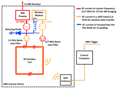
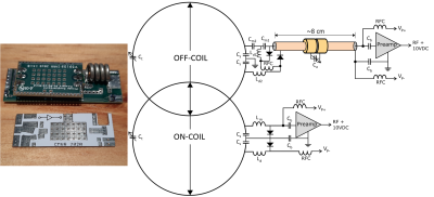
Figure 1: RF
currents flow on the integrated RF/wireless coil design for simultaneous MR
image acquisition (red) and wireless data transfer (orange), while a DC voltage
(blue) is applied to the PIN diode from a GPIO pin from the Wi-Fi transceiver module
for Q-spoiling.
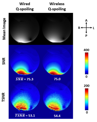
Figure 3: Gradient-echo
EPI mean images, SNR maps of the mean images, and temporal SNR (TSNR) maps of
the image time series acquired in a water phantom, showing no degradation in
image quality for wireless Q-spoiling using the iRFW coil compared to
conventional wired Q-spoiling.
-
Universally Sized, High-Resolution and ASSET Optimized AIR Cervical Coils Combined with a 48-Channel Head Coil for 3T MRI
Yun-Jeong Stickle1, Clyve Konrad Follante1, Mark Giancola1, David Anderson1, Fraser Robb1, Thomas Stickle1, Robert Stormont2, Holly Blahnik2, Ho-Joon Lee3, Young Han Lee4, and Darryl B. Sneag5
1GE Healthcare Coils, Aurora, OH, United States, 2GE Healthcare, Waukesha, WI, United States, 3Haeundae Paik Hospital, Busan, Korea, Republic of, 4Severance hospital, Yonsei University, Seoul, Korea, Republic of, 5Hospital for Special Surgery, New York, NY, United States
This study shows results for two different universally
sized AIR (Adaptive Imaging Receive) neck/cervical spine coils combined with a 48-Channel head coil to
provide higher SNR and improved acceleration compared to a conventional coil.
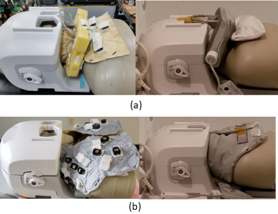
Fig. 1. Universally sized AIR 64-Channel
phased array head neck coils for carotid, head/neck and cervical spine MRI (a) Prototype1 16-Channel neck/cervical spine
anterior setup coil assembly with 48-Channel head coil (b) Prototype2
16-Channel neck/cervical spine posterior setup coil assembly with 48-Channel
head coil
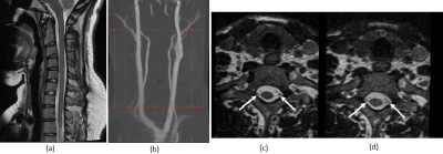
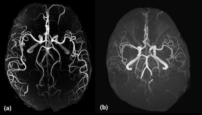
Fig. 5. (a) Sagittal T2,
20 cm FOV, 2mm slice thickness image and (b) MRA images obtained with the
protoytpe1 16-Channel neck/cervical spine coil with 48-Channel head coil. Axial
reformatted images of the cervical spine from a 3-D CUBE T2-weighted FSE sequence
(0.7mm isotropic) demonstrates improved SNR with the (c) protoytpe1 16-Channel
neck/cervical spine coil with 48-Channel head coil compared to the (d)
conventional coil. Note improved visualization of the intrathecal nerve
rootlets (arrows) with the prototype1 coil.
-
Development of a multiplexed ERETIC-RF array coil for quantitative whole brain 3D-MR spectroscopic imaging (MRSI)
Bijaya Thapa1,2, Bernhard Strasser1,2, Xianqi Li1,2, Jason Stockman1,2, Azma Mareyam1, Boris Keil3, Zhe Wang4, Stefan Carp1,2, Yulin V. Chang4, Lawrence Wald1,2, Philipp Hoecht Hoecht5, and Ovidiu Andronesi1,2
1Dept. of Radiology, MGH, A. A. Martinos Center for Biomedical Imaging, Charlestown, MA, United States, 2Harvard Medical School, Boston, MA, United States, 3Mittelhessen University of Applied Science, Giessen, Germany, 4Siemens Medical Solutions USA, Charlestown, MA, United States, 5Siemens Healthcare, Erlangen, Germany
An ERETIC method was integrated into 3D MRSI through the
hardware and software for quantitative brain metabolite imaging and compared
its result with the conventional internal water reference method. Bland-Altman
plot plotted to compare them which shows good agreement between these methods.
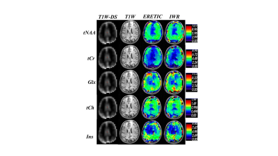
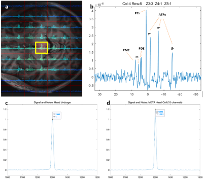
Fig3. Absolute
Metabolite concentration map in mMol unit obtained from ERETIC (3rd column)
and IWR (4th column) methods corresponding to the anatomical
MEMPRAGE image (2nd column) and MEMPRAG image down-sampled
to MRSI size (1st column ).
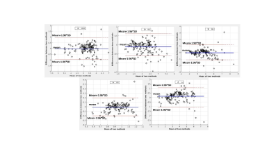
Fig4. Bland-Altman plots corresponding to the
metabolite concentration map shown in Fig.3, which indicates the agreement
between IWR and ERETIC methods.
-
New approach to Improve Sensitivity of Implantable NMR microprobe through Electrical Modelization
José Antonio BERNARDO1, Abel Rangel Trejo1, Lucas Werling2, Wilfried Uhring2, Luc Hebrard2, Youssef Zaim Wadghiri3, Christian Gontrand4, and Latifa Antonio Fakri-bouchet5
1Univ Lyon, CNRS, Université Claude Bernard Lyon 1, Institut des Sciences Analytiques, UMR 5280, Villeurbanne, France, 2Icube Laboratory, UMR –CNRS 7357, Université de Strasbourg, Strasbourg, France, 3Grossman School of Medicine, New York University, New York, NY, United States, 4INL(Institut des nanotechnologies de Lyon), INSA (Institut National des Sciences Appliquées) Lyon, CNRS, Université Claude Bernard Lyon1, Villeurbanne Cedex, France, 5Univ Lyon, CNRS, Université Claude Bernard Lyon 1, Institut des Sciences Analytiques, UMR 5280, INSA Lyon (Institut National des Sciences Appliquées), Villeurbanne, France
Through 3D-TLE platform, we can extract the
microprobe electrical parameters and then provide a complete electric model.
Thus, our original and accurate method aims to estimate the global resistive
losses from geometrical parameters.
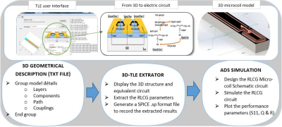
\(Fig.1\). Block diagrams of the simulation
methodology: TLE user interface to 3D microcoil model
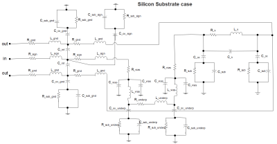
\(Fig.2\). The complete electric model of 3D NMR microcoil
prototype
-
Exploring parallel imaging performance for prostate imaging at 7T using a 72-channel receive array
Tijl van der Velden1, Mark Gosselink1, Ingmar Voogt2, Martijn Froeling1, Hans Hoogduin1, Dennis Klomp1, Bart Steensma1, and Alexander Raaijmakers1,3
1UMC Utrecht, Utrecht, Netherlands, 2Wavetronica, Utrecht, Netherlands, 3Biomedical Engineering, Eindhoven University of Technology, Eindhoven, Netherlands
An parallel imaging acceleration of a least a factor of 3 is
feasible with a 72-channel body array at 7T.
T2w
images with SENSE 1 (left), 2 (center) and 4 (right). Bottom row shows
magnification of the prostate. From an acceleration of 4 small artefacts are
observed, as well as the expected reduction in SNR.
3D
T1w acquisition of the lower body. Left, no SENSE acceleration, right: 3x3
SENSE acceleration. Artefacts are predominately in the peripheral region of the
body.
-
Coaxial coil modules as building blocks of individually arranged receive-only coil arrays
Michael Obermann1, Sigrun Roat1, and Elmar Laistler1
1High Field MR Center, Center for Medical Physics and Biomedical Engineering, Medical University of Vienna, Vienna, Austria
A proof of principle for a truly modular ultra-lightweight
multi-purpose flexible receive array made from coaxial coil elements was
demonstrated by showing three 4-channel modules arranged in different array
configurations.
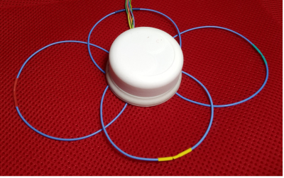
Fig. 1: 4-ch coaxial coil module. The compact cylindrical housing (diameter
= 5.2 cm, height 3.2 cm) surrounds the PCBs with all electrical components and four
preamplifiers.
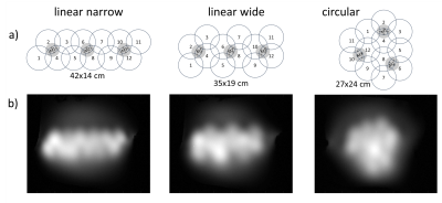
Fig. 2: a)
Differently arranged 12-ch layouts built from the same modules M1, M2 and M3. b) MR images (GRE2D) acquired on a flat
phantom in a slice at a distance of 5 cm to the coil arrays. The distance from
the arrays to the phantom is around 5 mm.